
High-pressure angle valves fail 30% faster in steam applications when flow-induced vibration (FIV) goes undiagnosed. Unlike the obvious signs of seat leakage or packing failure, valve vibration operates as a silent destroyer—gradually weakening internal components, loosening connections, and creating microscopic stress fractures that lead to catastrophic failure without warning.
For maintenance engineers managing steam distribution systems above 600 psi, understanding the physics behind FIV in angle valves isn’t academic; it’s critical for preventing unplanned downtime, reducing replacement costs, and ensuring system reliability. This technical analysis examines why the L-shaped flow path in angle valves creates unique vibration challenges and provides a diagnostic framework for distinguishing flow-induced vibration from cavitation.
Why Angle Valves Generate More Vibration Than Straight-Through Designs
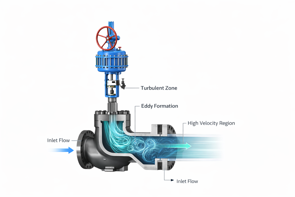
The fundamental issue lies in the 90-degree flow redirection that defines an angle valve. When high-velocity steam encounters this sharp directional change, it creates a phenomenon known as separated flow where the fluid stream detaches from the valve body wall, forming recirculating eddies.
The Physics of L-Shaped Flow Disruption
In a high-pressure angle valve, the flow pattern creates three distinct vibration mechanisms:
| Vibration Mechanism | Frequency Range (Hz) | Primary Cause | Mode de défaillance |
|---|---|---|---|
| Vortex Shedding | 15-150 Hz | Alternating vortices behind valve trim | Trim erosion, seat damage |
| Turbulent Buffeting | 5-50 Hz | Random pressure fluctuations from eddies | Body cracking, bonnet loosening |
| Acoustic Resonance | 100-1000 Hz | Standing wave formation in the L-turn | Stem fatigue, actuator damage |
The most damaging occurs when the vortex shedding frequency approaches the natural frequency of the valve components. This resonance condition amplifies vibration amplitude exponentially, accelerating fatigue failure.
Critical Insight: The Reynolds Number Threshold
Steam flow becomes significantly turbulent in angle valves when the Reynolds number exceeds 50,000. For a 3-inch angle valve with 600 psi steam, this threshold is reached at approximately 15,000 lb/hr mass flow rate—a common operating condition that many engineers don’t realize is in the high-risk vibration zone.
Diagnostic Framework: FIV vs. Cavitation
Valve vibration troubleshooting requires distinguishing between flow-induced vibration et cavitation, as both produce similar audible and tactile symptoms but require different solutions.
Field Identification Checklist
Flow-Induced Vibration (FIV) Indicators:
- Frequency: Consistent, measurable vibration at 15-150 Hz
- Sound: Steady humming or whining, increases with flow rate
- Pressure Condition: Occurs even when downstream pressure is well above vapor pressure
- Temperature Effect: Vibration intensity varies with steam temperature (higher temperature = lower density = higher velocity)
- Flow Dependency: Directly proportional to mass flow rate through the valve
Cavitation Indicators:
- Frequency: Random, crackling vibrations (2000-10000 Hz)
- Sound: “Popping corn” or grinding noise
- Pressure Condition: Only occurs when pressure drop approaches fluid vapor pressure
- Temperature Effect: More severe at higher temperatures (closer to saturation)
- Flow Dependency: Begins at a specific flow rate threshold, then remains constant
Quantitative Measurement Protocol
Professional diagnosis requires vibration measurement at three critical points:
- Valve Body (Horizontal): Mount accelerometer on the outlet side, perpendicular to flow direction
- Bonnet (Vertical): Measure along the stem axis to detect actuator resonance
- Upstream Piping (6 diameters): Baseline measurement to isolate valve-specific vibration
| Vibration Level (mm/s RMS) | Condition Assessment | Mesures recommandées |
|---|---|---|
| < 2.8 | Bon | Continue normal operation |
| 2.8 – 7.1 | Acceptable | Monitor quarterly |
| 7.1 – 18 | Unsatisfactory | Plan corrective action within 6 months |
| > 18 | Unacceptable | Immediate shutdown and repair |
Engineering Solutions for FIV Mitigation
Once flow-induced vibration is confirmed, several engineering approaches can extend valve life and improve system reliability.
1. Velocity Limitation Through Proper Sizing
The most effective prevention method is maintaining steam velocity below the critical threshold. For high-pressure angle valves in steam service:
- Maximum Inlet Velocity: 100 ft/sec (30 m/s) for pressures above 400 psi
- Outlet Velocity Limit: 150 ft/sec (45 m/s) to prevent downstream erosion
- Cv Sizing Rule: Select valve size where maximum operating flow uses 70-80% of rated Cv
2. Advanced Trim Designs
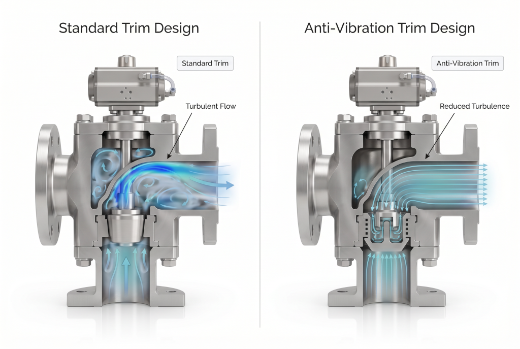
Modern anti-vibration valve trim incorporates several technologies to reduce turbulence:
- Streamlined Plug Geometry: Reduces wake formation and vortex shedding
- Multi-Stage Pressure Reduction: Staggers pressure drops to minimize single-point turbulence
- Flow Straightening Vanes: Redirects flow smoothly through the 90-degree turn
3. Structural Reinforcement
For existing installations where replacement isn’t feasible, structural modifications can reduce vibration transmission:
- Heavier Wall Construction: Increases body stiffness and raises natural frequency above excitation range
- Reinforced Bonnet Design: Prevents stem misalignment under vibrational loads
- Vibration Dampers: External devices that absorb and dissipate vibrational energy
Cost Impact Analysis: Prevention vs. Replacement
The economic case for addressing FIV in steam systems becomes clear when comparing prevention costs against failure consequences:
| Cost Component | Preventive Action | Failure Replacement |
|---|---|---|
| Material Cost (4″ Class 1500) | Moderate cost (anti-vibration trim) | High cost (complete valve replacement) |
| Labor (Installation) | Low cost (trim change-out) | High cost (full replacement) |
| Downtime Impact | Minimal (planned maintenance window) | Severe (unplanned emergency shutdown) |
| Total Economic Impact | Significantly Lower | 5x Higher Than Prevention |
Selecting FIV-Resistant Angle Valves
When specifying new high-pressure angle valves for steam service, several design criteria minimize vibration risk:
Critical Specification Requirements:
- Body Wall Thickness: Minimum 25% above standard pressure rating to increase stiffness
- Stem Diameter: Oversized by 15-20% for high-vibration applications
- Streamlined Internal Geometry: Smooth transitions, no sharp edges in flow path
- Reinforced Seat Ring: Welded rather than threaded for high-vibration environments
- Material Selection: Duplex stainless steel for enhanced fatigue resistance
For applications where standard commercial valves are insufficient, BCST Valve’s heavy-duty angle valve designs incorporate specialized anti-vibration features specifically engineered for high-velocity steam service.
Conclusion: From Silent Killer to Predictable Performance
Flow-induced vibration en high-pressure angle valves transforms from an invisible threat into a manageable engineering challenge once properly understood and diagnosed. The key lies in recognizing that the L-shaped flow path—while offering significant installation advantages—inherently creates turbulence that must be controlled through proper sizing, advanced trim design, or structural reinforcement.
For maintenance teams currently experiencing unexplained angle valve failures in steam systems, implementing the diagnostic framework outlined here can identify whether FIV is the root cause. Early intervention through vibration monitoring and preventive solutions delivers substantial economic benefits compared to reactive replacement strategies.
Experiencing Unexplained Angle Valve Failures in Your Steam System?
BCST Valve’s engineering team provides technical consultation and FIV assessment services to diagnose valve vibration issues and recommend appropriate mitigation strategies for your specific operating conditions.


 English
 Arabic
 Russian
 French
 Spanish