
Industrial Gas Flow Control
Gas Damper Manufacturer
BCST manufactures industrial gas dampers for isolating, regulating, balancing and diverting flue gas, process gas, combustion gas and ventilation gas. Each damper is engineered around the duct dimensions, gas composition, temperature, pressure, particulate loading, leakage requirement and control method.
- Butterfly, louver, guillotine and diverter designs
- Isolation, modulation and gas-path switching functions
- Round, square and rectangular duct configurations
- High-temperature, corrosive and dust-service options
- Manual, electric, pneumatic or hydraulic operation
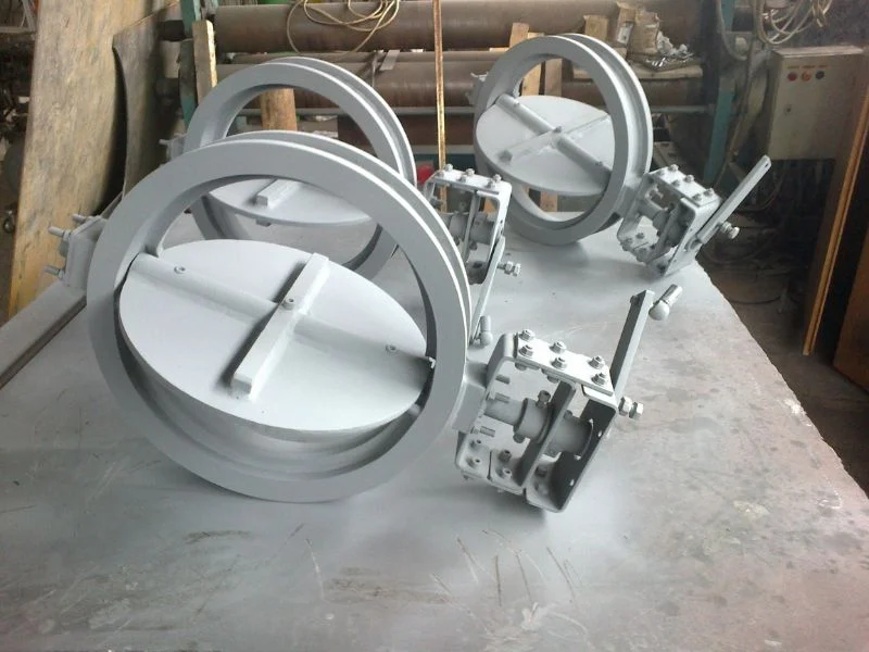
Gas-Path Isolation
Separate ducts and process equipment during maintenance, switching or shutdown.
Régulation du débit
Control gas volume, pressure, draft and distribution through engineered blade movement.
Harsh-Service Design
Configure materials and components for heat, corrosion, dust and thermal cycling.
Custom Manufacturing
Match dimensions, connections, actuators and controls to the project.
Product Collection
Industrial Gas Damper Configurations
Select the damper type according to its operating function, duct geometry, gas conditions and required isolation performance.
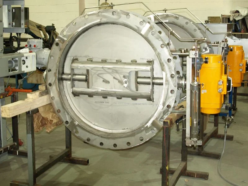
Butterfly Gas Damper
A rotating central blade provides compact isolation or modulation in round and engineered gas ducts.
- Compact face-to-face dimension
- Open-close or modulating duty
- Manual or automated operation
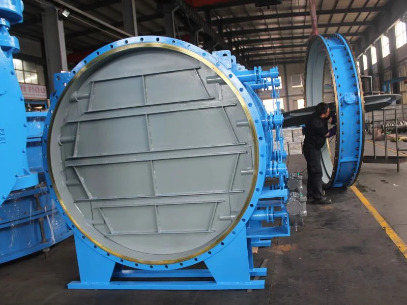
Louver Gas Damper
Multiple linked blades distribute gas control across large square or rectangular duct sections.
- Parallel or opposed blades
- Large duct capability
- Isolation or regulation
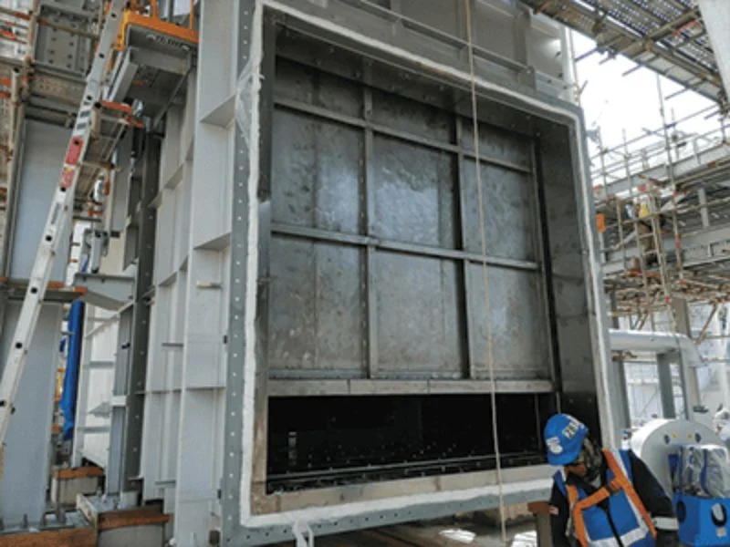
Guillotine Gas Damper
A sliding blade provides dedicated isolation and withdraws from the gas path when fully open.
- Clear open gas path
- Maintenance isolation
- Single or double blade options
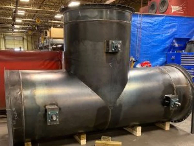
Gas Diverter Damper
A coordinated blade or flap arrangement directs process gas between alternative equipment paths.
- Gas-path switching
- Bypass system applications
- Coordinated actuator control
Product Comparison
Choose the Appropriate Gas Damper
| Damper Type | Fonction principale | Typical Installation | Main Advantage | Selection Priority |
|---|---|---|---|---|
| Butterfly damper | Isolation or regulation | Round or engineered duct | Compact and economical construction | Torque and acceptable leakage |
| Parallel-blade louver damper | Isolation or directional control | Large square or rectangular duct | Rapid change in gas-flow area | Isolation duty and downstream flow pattern |
| Opposed-blade louver damper | Modulating control | Large square or rectangular duct | Balanced gas distribution | Control range and system resistance |
| Guillotine damper | Dedicated process isolation | Round, square or rectangular duct | Blade clears the open gas path | Isolation and installation clearance |
| Diverter damper | Gas-path switching | Branch, bypass or equipment train | Directs flow between alternative paths | Switching sequence and sealing |
Engineering Approach
Designed Around the Gas Conditions
Gas composition and operating conditions affect the damper body, blades, shafts, bearings, seals, actuator and control accessories. A reliable selection starts with complete process data.
- Define the function: Confirm isolation, regulation, balancing or diversion.
- Review the medium: Identify gas composition, moisture, contaminants and safety concerns.
- Confirm operating limits: Provide flow, pressure, temperature and transient conditions.
- Select the construction: Choose the damper type, materials and sealing arrangement.
- Size the actuator: Evaluate aerodynamic torque, friction, deposits and safety margin.
- Verify the interfaces: Match the duct, actuator and controls to the plant system.
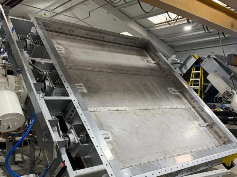
Gas Compatibility
Select materials and seals for corrosive, wet, toxic or contaminated gas.
Leakage Requirement
Specify the maximum acceptable leakage and required isolation method.
Operating Safety
Define fail position, travel time, position feedback and interlock requirements.
Technical Configuration
Configurable Gas Damper Specifications
Final dimensions, materials and operating limits depend on the selected design and approved project data.
| Paramètres | Available Engineering Options | Selection Basis |
|---|---|---|
| Duct shape | Round, square or rectangular | Existing duct geometry and installation space |
| Damper size | Standard and project-specific dimensions | Flow rate, gas velocity and duct opening |
| Operating function | Isolation, modulation, balancing or diversion | Plant operating philosophy |
| Design pressure | Positive or negative gas-pressure design | Normal, maximum and upset pressure |
| Température de fonctionnement | Ambient to high-temperature construction | Normal, maximum and transient temperatures |
| Body material | Carbon steel, stainless steel or specified alloy | Gas chemistry, corrosion and temperature |
| Blade design | Flat, reinforced, airfoil, sliding or engineered profile | Damper type, size and pressure differential |
| Seal arrangement | Clearance, metal, flexible or purge-assisted seal | Gas composition, temperature and leakage limit |
| Connexion | Flanged, welded, wafer-style or custom interface | Duct construction and installation method |
| Actionnement | Manual, electric, pneumatic or hydraulic | Torque, thrust, operating time and plant utilities |
Customer Priorities
Critical Questions Before Damper Selection
Process Conditions
- What is the gas composition?
- Does the gas contain moisture or condensate?
- What are the normal and maximum temperatures?
- Is the duct under positive or negative pressure?
- Does the gas contain dust, ash or sticky deposits?
- Are any components corrosive, toxic or combustible?
Functional Requirements
- Will the damper isolate, regulate or divert flow?
- What closed-position leakage is acceptable?
- Is purge or sealing gas available?
- What operating time and cycle frequency are required?
- Which actuator utility is available?
- What fail position, alarms and feedback are required?
Leakage & Isolation
Select the Correct Sealing Arrangement
A closed gas damper is not automatically gas-tight. Leakage depends on the blade geometry, seal design, frame rigidity, pressure differential, temperature and actuator output.
- Clearance seal: Suitable where controlled closed-position leakage is acceptable.
- Metal contact seal: Improves isolation for compatible temperatures and operating cycles.
- Flexible seal: Supports lower leakage where the material is suitable for the process gas.
- Double-blade system: Creates an intermediate cavity between two isolation elements.
- Purge-assisted seal: Uses clean gas or air to establish an enhanced pressure barrier.
High-Temperature Service
Managing Heat and Thermal Expansion
High-temperature gas can expand blades, shafts and frames at different rates. The damper must retain sufficient clearance, strength and alignment throughout startup, operation and shutdown.
- Temperature-compatible body and blade materials
- Engineered cold and hot operating clearances
- Reinforced blades for thermal and pressure loads
- External bearings and protected drive components
- Insulation, heat-shield or refractory options
- Expansion allowances at duct interfaces
- Evaluation of rapid temperature changes
Sélection des matériaux
Materials for Different Gas Conditions
| Material Option | Typical Application | Engineering Consideration |
|---|---|---|
| Acier au carbone | Compatible dry gas at moderate temperature | Corrosion allowance and external environment |
| Acier inoxydable | Corrosive, wet or elevated-temperature gas | Gas chemistry, chlorides and temperature limits |
| Heat-resistant alloy | Furnace, kiln and demanding hot-gas systems | Oxidation, strength and thermal cycling |
| Protective coating | Specified internal or external corrosion protection | Temperature and chemical compatibility |
| Refractory lining | Additional thermal or abrasion protection | Added weight, anchoring and thermal movement |
| Replaceable wear protection | Abrasive ash, dust or solid particles | Wear pattern and maintenance access |
Actuation & Controls
Operating Options for Plant Integration
Manual Operation
Gearbox, handwheel or chain-wheel operation for infrequent local isolation.
- Simple local operation
- Position-locking options
- Suitable for low cycle frequency
Actionnement électrique
Motorized operation for remote isolation, regulation or gas-path switching.
- Open-close or modulating duty
- Limit and torque switch options
- Position feedback available
Actionnement pneumatique
Fast and repeatable operation using the plant instrument-air supply.
- Double-acting or fail-position options
- Solenoid and positioner accessories
- Suitable for automated systems
Hydraulic Actuation
High output force for large dampers and demanding service conditions.
- High torque or thrust capability
- Controlled operating speed
- Engineered hydraulic package
Application Matrix
Typical Industrial Gas Damper Applications
| Industry or System | Gas Service | Damper Function | Key Selection Concern |
|---|---|---|---|
| Production d'électricité | Flue gas and combustion gas | Isolation, bypass and draft control | Temperature, fly ash and reliability |
| Cement production | Kiln, cooler and mill gas | Flow regulation and equipment isolation | Abrasion, deposits and high temperature |
| Steel and metallurgy | Furnace and process gas | Gas switching, isolation and control | Thermal cycling and gas composition |
| Traitement chimique | Process and exhaust gas | Isolation and flow regulation | Corrosion, toxicity and external leakage |
| Raffinage | Combustion and process exhaust gas | Gas-path isolation and control | Operating safety and sealing performance |
| Waste treatment | Incineration and treatment gas | Gas-path control and isolation | Temperature and corrosive condensate |
| Emission-control systems | Gas entering treatment equipment | Bypass, balancing and isolation | Process continuity and leakage limit |
Selection Checklist
Information Required for Gas Damper Engineering
Process Data
- Gas name, composition and density
- Normal, minimum and maximum flow rate
- Operating and design temperature
- Positive or negative design pressure
- Moisture, condensation and corrosive components
- Dust concentration and particle characteristics
Mechanical & Control Data
- Duct shape and internal dimensions
- Flange drilling or connection details
- Isolation, regulation or diversion duty
- Maximum acceptable closed-position leakage
- Available actuator utility and control signal
- Fail position, operating time and feedback requirements
Manufacturer Support
From Process Data to Final Damper Configuration
1. Application Review
We review the gas composition, flow, temperature, pressure, duct dimensions and operating function.
2. Mechanical Design
The body, blades, shafts, seals, bearings and connections are configured for the service.
3. Actuator Selection
Required torque or thrust, speed, fail position and control accessories are evaluated.
4. Documentation
Approved drawings, technical data and inspection documents are prepared for the order scope.
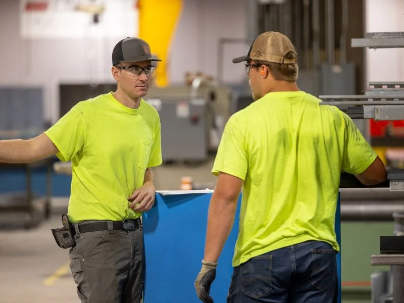
Quality Control
Inspection Before Shipment
Inspection and testing are completed according to the approved specification, selected design and purchase-order requirements.
- Material and component verification
- Dimensional and visual inspection
- Blade, shaft and bearing alignment checks
- Linkage or guide inspection
- Full-stroke operational testing
- Actuator and position-feedback verification
- Leakage testing where specified
- Coating, marking and packing inspection
Installation & Maintenance
Protect Alignment and Operating Reliability
Installation
- Confirm the specified gas-flow direction
- Prevent duct loads from distorting the frame
- Maintain actuator and bearing access
- Verify blade or flap clearance
- Allow for thermal movement where required
Commissioning
- Remove construction debris from the duct
- Confirm complete and smooth travel
- Set open and closed position limits
- Verify actuator direction and feedback
- Test purge functions where specified
Maintenance
- Inspect blades, seals and gas-path deposits
- Check bearings, guides and linkages
- Verify actuator mounting and fasteners
- Exercise infrequently operated dampers
- Investigate abnormal torque or vibration
Send Us Your Gas Damper Data
Provide the duct dimensions, gas composition, flow rate, pressure, temperature, particulate conditions, leakage requirement, operating function and actuator preference. Our engineers will help configure a suitable gas damper.
Questions fréquemment posées
Gas Damper FAQ
What is an industrial gas damper?
It is a blade-operated device used to isolate, regulate, balance or divert gas flow inside an industrial duct system.
Which gas damper type should I select?
Butterfly dampers offer compact control, louver dampers suit large ducts, guillotine dampers provide dedicated isolation and diverter dampers switch between gas paths.
Can a gas damper provide zero leakage?
A standard single-blade damper normally permits some leakage. Enhanced isolation may require special seals, double blades or a purge-assisted arrangement.
Can the damper regulate gas flow?
Butterfly and opposed-blade louver dampers can be configured for modulation. Performance should be evaluated against the system resistance and required control range.
Can it handle corrosive gas?
Corrosive-gas service requires suitable body, blade, shaft and seal materials. Complete gas composition and condensation data should be provided for review.
Can BCST manufacture high-temperature gas dampers?
High-temperature configurations are available. Materials, clearances, bearings, seals and thermal expansion must be evaluated for the stated conditions.
Which actuator should be selected?
The selection depends on torque or thrust, operating speed, control duty, cycle frequency, fail position and available plant utilities.
What information is required for quotation?
Provide duct dimensions, gas composition, flow, pressure, temperature, particle loading, leakage requirement, operating function, connection details and actuator preference.
 English
 Arabic
 Russian
 French
 Spanish