
Engineering Services
After-Sales Support for Industrial Flow Products
BCST supports customers after delivery with installation guidance, commissioning preparation, troubleshooting assistance, spare-parts identification and replacement recommendations. Support is based on the supplied product configuration, operating data and available service records.
- Installation guidance before site assembly
- Commissioning preparation and functional checks
- Structured troubleshooting based on operating evidence
- Spare and wear-part identification
- Replacement recommendations for existing equipment

Install Correctly
Confirm orientation, alignment, access and connection requirements.
Commission Methodically
Check the system, product movement and operating sequence before service.
Diagnose with Evidence
Use operating data, photographs and service history to identify likely causes.
Plan the Lifecycle
Prepare suitable spare parts and replacement options before urgent demand.
Support Scope
Support Through the Product Lifecycle
The available support method depends on the product, site conditions, project scope and information supplied by the customer.

Installation Guidance
Review installation orientation, connections, alignment, support, access and product-protection requirements.
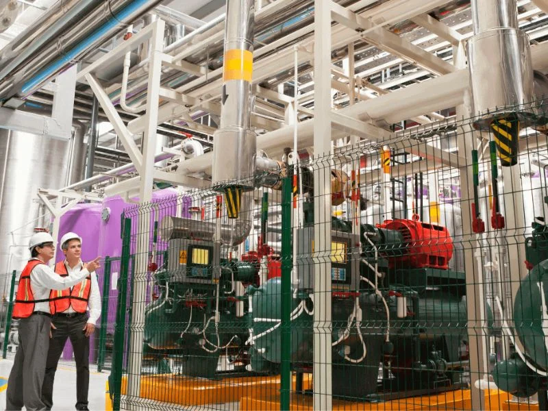
Commissioning Support
Provide preparation checklists and assist with product-specific functional verification before operation.

Dépannage
Review symptoms, operating conditions, photographs, measurements and maintenance history.
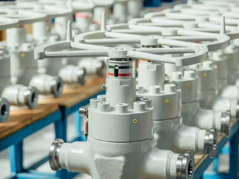
Spare Parts
Identify compatible seals, seats, screens, sleeves, trim, actuators and other service components.

Replacement Recommendation
Review existing equipment data and current process conditions before proposing a replacement configuration.

Maintenance Planning
Use service history and wear patterns to improve inspection intervals and spare-parts planning.
Support Matrix
What to Provide for Faster Support
| Support Request | Customer Information | BCST Review | Typical Output |
|---|---|---|---|
| Installation Guidance | Product tag, drawing, piping layout and site photographs | Orientation, connection, support and access | Installation checklist or guidance |
| Commissioning Support | System status, operating sequence and utility conditions | Pre-start checks and functional requirements | Commissioning checklist or recommendations |
| Dépannage | Symptoms, process data, images, video and service history | Likely causes and safe inspection steps | Corrective-action recommendations |
| Spare Parts | Model, serial number, tag and photographs | Compatibility with the supplied configuration | Recommended spare-parts list |
| Replacement Recommendation | Existing datasheet, dimensions and current operating data | Interface, duty and material suitability | Proposed replacement configuration |
Installation Guidance
Prepare the System Before Installation
Correct installation helps prevent leakage, distortion, restricted movement and premature wear. Product-specific instructions and approved drawings should be reviewed before work begins.
Typical Pre-Installation Checks
- Verify model, size, rating, materials and flow direction
- Inspect the product for storage or transport damage
- Remove shipping covers only when the system is ready
- Flush debris from the pipeline, duct or tank connection
- Check alignment without forcing the product into position
- Confirm gasket, fastener and flange compatibility
- Provide adequate support and maintenance clearance
- Protect internal parts from welding debris and contamination
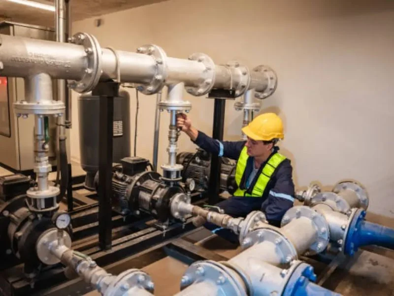
Installation Priorities
Product-Specific Installation Considerations
| Product Category | Installation Priority | Common Risk to Avoid |
|---|---|---|
| Tank Protection Equipment | Vertical installation, clear vent path and accessible inspection location | Blocked outlets, incorrect set-point product or contaminated seats |
| Flame Arrestor | Correct model, orientation and location within documented limits | Using an installation arrangement not covered by applicable evidence |
| Strainer or Filter | Correct flow direction, screen access, drain and differential-pressure points | Insufficient basket-removal space or reversed flow |
| Industrial Damper | Duct alignment, support, shaft orientation and thermal movement | Frame distortion or external loading that prevents blade travel |
| Pinch or Slurry Valve | Correct orientation, actuator settings and sleeve or liner protection | Pipeline stress or trapped solids that damage wear parts |
| Vanne actionnée | Correct utilities, control signal, fail action and accessory wiring | Incorrect rotation, pressure, voltage or travel limits |
Check Before Connecting
Verify identity, orientation, condition and system cleanliness.
Protect During Installation
Prevent distortion, contamination, impact and excessive piping loads.
Keep Access Available
Allow room for inspection, cleaning and replacement of service components.
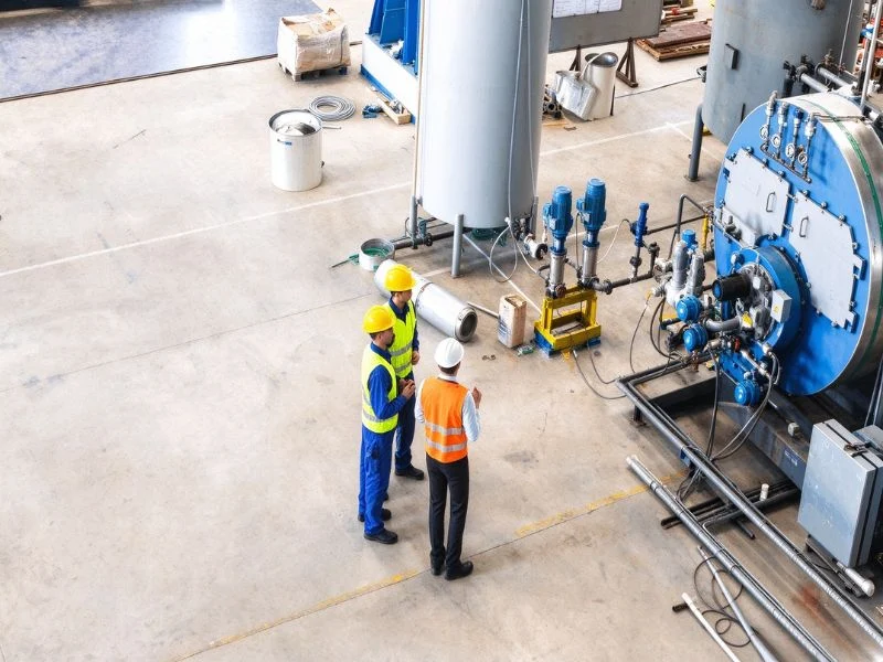
Commissioning Support
Verify the Product Before Process Operation
Commissioning should be performed under an approved site procedure by qualified personnel. BCST can support the preparation and product-specific review within the agreed scope.
- Confirm that installation matches the approved drawing.
- Check that temporary shipping restraints have been removed.
- Verify pipeline or duct cleanliness.
- Confirm actuator utilities and control signals.
- Operate the product through its full travel where safe.
- Check local and remote position indication.
- Introduce pressure, flow or temperature gradually.
- Inspect connections, packing and covers for leakage.
- Record initial settings and operating observations.
Commissioning Matrix
Typical Functional Checks
| Vérifier | What to Verify | Possible Evidence |
|---|---|---|
| Product Identification | Tag, model, size, rating and material configuration | Nameplate and approved datasheet |
| Mechanical Travel | Free movement between required positions | Local observation and position indicator |
| Actuator Function | Direction, speed, torque and travel limits | Functional test record |
| Control Accessories | Solenoid, positioner, switches and feedback signal | Control-system response |
| Fail Action | Specified fail-open, fail-closed or fail-in-place behavior | Approved site test where safe and required |
| External Leakage | Connections, covers, packing and instrument ports | Site inspection after gradual pressurization |
| Operating Baseline | Initial position, pressure, differential pressure and cycle time | Commissioning record |
Dépannage
Diagnose the Cause Before Replacing Parts
Symptoms such as leakage, high operating torque or unstable performance can result from the product, installation or process. A structured review helps avoid replacing components without addressing the actual cause.
Information to Collect
- Product tag, model and serial number
- Date of installation and operating hours
- Description of the symptom and when it occurs
- Current flow, pressure, temperature and medium
- Photographs of the product and installation
- Video of the operating problem where safe
- Actuator pressure, voltage or control signal
- Recent maintenance and replaced components

Troubleshooting Guide
Common Symptoms and Initial Checks
| Symptôme | Cause possible | Initial Check | Possible Next Step |
|---|---|---|---|
| External leakage | Loose connection, damaged gasket or packing wear | Locate the exact leakage point under safe conditions | Depressurize and inspect the affected seal |
| Internal leakage | Seat damage, contamination or incorrect closure | Check process debris and full travel | Inspect and clean or replace sealing parts |
| High operating torque | Deposits, misalignment, pressure load or damaged internals | Review pressure differential and actuator output | Isolate and inspect moving components |
| Incomplete travel | Incorrect limit setting, obstruction or insufficient actuator force | Check signals, utilities and mechanical stops | Correct settings or inspect for blockage |
| Unstable control | Oversizing, positioner setting or process variation | Review valve position, signal and process trend | Evaluate sizing and control configuration |
| Rapid wear | Abrasion, corrosion, cavitation or excessive velocity | Inspect the wear pattern and current process data | Review materials, size and operating conditions |
| Frequent filter blockage | Unexpected debris load or opening that is too fine | Record differential pressure and collected debris | Review element size, area and cleaning method |
Make the System Safe
Isolate stored energy and follow approved site procedures before inspection.
Record the Evidence
Capture operating conditions, symptoms and wear patterns before disassembly.
Correct the Root Cause
Address process, installation and product factors—not only the failed component.
Spare Parts
Identify Parts from the Original Configuration
Product model alone may not identify every component. Size, material, seat design, actuator and production configuration should be confirmed before ordering spares.
Common Spare and Wear Parts
- Seats, sleeves, liners and sealing rings
- Packing, gaskets and O-rings
- Screens, baskets and filter elements
- Pallets, seals and internal guides
- Gates, stems, shafts and bearings
- Actuator repair components
- Solenoid valves, switches and positioners
- Product-specific fasteners and accessories
Spare-Parts Planning
Recommended Spare-Part Categories
| Spare Category | Typical Components | Planning Consideration |
|---|---|---|
| Commissioning Spares | Gaskets, packing and selected soft seals | Potential installation or startup replacement |
| Operational Spares | Seats, sleeves, screens and sealing kits | Expected wear and routine maintenance interval |
| Critical Spares | Unique trim, actuator or internal assemblies | Lead time and consequence of plant shutdown |
| Long-Term Spares | Wear liners, gates, shafts and major service components | Expected lifecycle and storage requirements |
| Instrument Spares | Positioners, solenoids, switches and regulators | Site standardization and control-system compatibility |
Replacement Recommendation
Replace the Function, Not Only the Dimensions
A replacement product should match the piping interface and satisfy the current operating conditions. Existing dimensions alone are not enough when the process or duty has changed.
Information Required
- Existing manufacturer, model and product tag
- Datasheet, drawing and nameplate photograph
- Face-to-face and connection dimensions
- Current medium, flow, pressure and temperature
- Actuator type, signal and fail position
- Reason for replacement and failure history
- Changes in the process since original installation
- Required documents and inspection scope

Replacement Review
Compatibility Points to Confirm
| Compatibility Item | What Must Be Confirmed | Risk if Overlooked |
|---|---|---|
| Process Duty | Medium, flow, pressure, temperature and required function | Unsuitable product performance or reduced service life |
| Dimensions | Size, face-to-face, height and maintenance clearance | Product does not fit the existing installation |
| Connections | Flange, drilling, facing, pipe or duct interface | Field modification or connection mismatch |
| Matériaux | Body, trim, seat, liner, packing and gasket | Corrosion, abrasion or chemical incompatibility |
| Actionnement | Power, signal, torque, orientation and fail action | Incorrect movement or control-system incompatibility |
| Performance | Capacity, pressure loss, set point, leakage or filtration rating | System does not meet current operating requirements |
Need Technical Support for Installed Equipment?
Send the product tag, nameplate, photographs, current process data and a clear description of the request. Our team will review the available information and recommend the next step.
Support Request Checklist
Information That Helps Us Respond
Product Identification
- Product type and model
- Size and pressure rating
- Serial number or product tag
- Original purchase-order reference
- Nameplate photograph
- General installation photographs
Operating Information
- Process medium and composition
- Current flow, pressure and temperature
- Date the issue first appeared
- Operating symptoms and frequency
- Recent maintenance activities
- Measurements, photographs or safe operating video
Questions fréquemment posées
After-Sales Support FAQ
What information should I provide for support?
Provide the product tag, nameplate, model, photographs, operating conditions, symptom description and available purchase or service records.
Can BCST provide installation guidance?
Yes. Product-specific guidance can be provided from the approved drawings and manuals. Site installation must be performed under the customer’s authorized procedures.
What does commissioning support include?
Support may include preparation checklists, configuration review and product-specific functional checks within the agreed project scope.
Can a problem be diagnosed from photographs?
Photographs can help identify visible conditions, but reliable troubleshooting normally also requires operating data, product identification and maintenance history.
How do I identify the correct spare part?
Provide the model, size, serial number, original order reference and photographs. Material and configuration details may also be required.
Can non-original parts be used?
Unverified parts may differ in material, dimensions or performance. Compatibility should be confirmed before installation.
Can BCST recommend a replacement for another brand?
A replacement can be reviewed when the existing dimensions, connections, operating data, required function and available technical records are provided.
When should equipment be replaced instead of repaired?
Replacement may be appropriate when critical pressure parts are damaged, compatible spares are unavailable, process conditions have changed or repair is no longer practical.
 English
 Arabic
 Russian
 French
 Spanish