
Startup Pipeline Protection
Cone Strainer Manufacturer
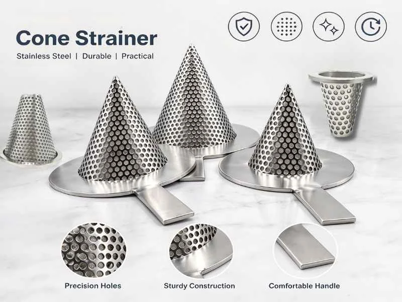
BCST Valve manufactures cone strainers for removing welding slag, rust, scale and construction debris during pipeline flushing, commissioning and startup.
Installed between two pipe flanges, the conical element provides more filtration area than a flat temporary screen while requiring no permanent strainer housing.
- Pointed-cone and truncated-cone configurations
- Forward-flow and reverse-flow designs
- Perforated plate and mesh-lined construction
- Carbon steel and stainless steel options
- Custom flange rings, openings and cone lengths
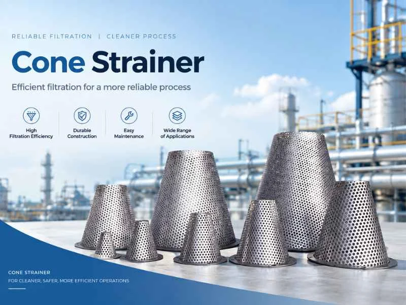
Startup Protection
Captures construction debris before it reaches critical equipment.
Large Filtration Area
The conical shape provides more screen area than a flat plate.
Compact Installation
Fits between pipeline flanges without a permanent housing.
Custom Construction
Dimensions and openings can match project requirements.
Product Collection
Cone Strainer Types
Select the cone shape, flow direction and screen construction according to pipeline space and startup conditions.
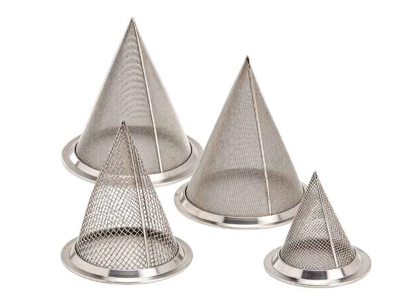
Pointed Cone Strainer
A full-length conical element designed to provide a large filtration surface for pipeline flushing and startup.
- Large effective filtration area
- High dirt-holding capacity
- Metric and ASME flange options
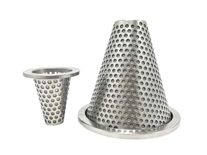
Truncated Cone Strainer
A flat-ended cone that reduces element length while retaining more area than a flat temporary screen.
- Reduced installation length
- Reinforced end construction
- Suitable for restricted pipe sections
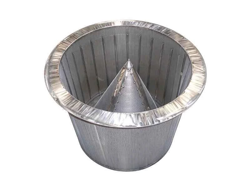
Reverse Cone Strainer
A conical element installed in the opposite orientation when flow loading or available pipeline space requires it.
- Alternative cone orientation
- Flow-direction review required
- Reinforced support options
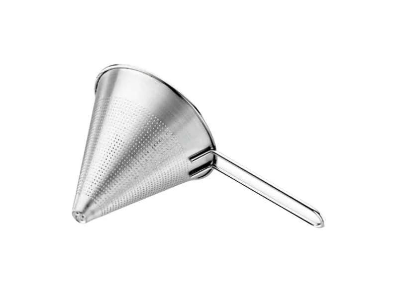
Perforated Cone Strainer
A robust perforated plate element for capturing coarse debris during flushing and commissioning.
- High mechanical strength
- Coarse particle removal
- Multiple perforation patterns
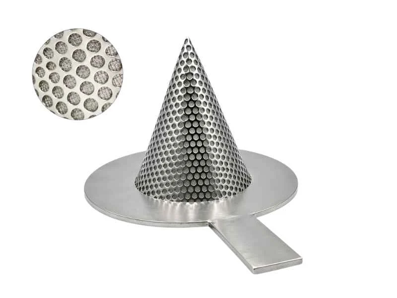
Mesh-Lined Cone Strainer
A perforated support cone lined with woven wire mesh for smaller particle retention.
- Medium or fine filtration
- Supported mesh construction
- SS304 and SS316 mesh options
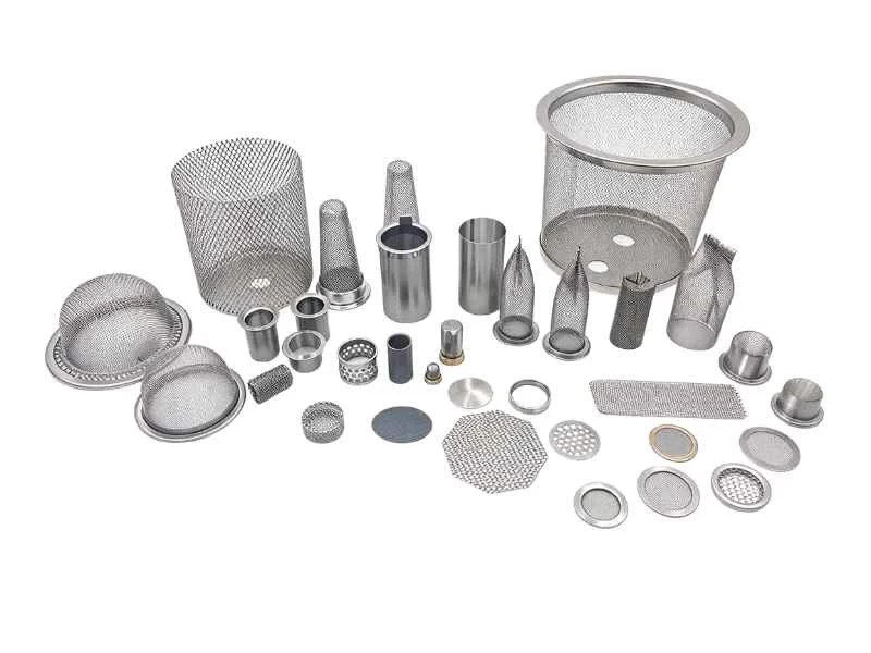
Custom Cone Strainer
A project-specific element for special flange dimensions, materials, pressure drops or filtration requirements.
- Custom cone length and angle
- Special filtration openings
- Alternative support designs
Product Comparison
Choose the Appropriate Cone Strainer
The preferred configuration depends on available pipe length, debris loading, required opening and allowable pressure drop.
| Cone Strainer Type | Filtration Area | Required Length | Typical Construction | Best Suited For |
|---|---|---|---|---|
| Pointed Cone | Haut | Long | Perforated or mesh lined | Higher debris loading |
| Truncated Cone | Medium to high | Medium | Perforated or mesh lined | Restricted installation length |
| Reverse Cone | Haut | Long | Reinforced construction | Alternative flow loading |
| Perforated Cone | Haut | Model dependent | Single perforated layer | Coarse startup filtration |
| Mesh-Lined Cone | Haut | Model dependent | Perforated support with mesh | Smaller particle retention |
| Custom Cone | Project specific | Project specific | Engineered construction | Special commissioning conditions |
Operating Principle
How a Cone Strainer Works
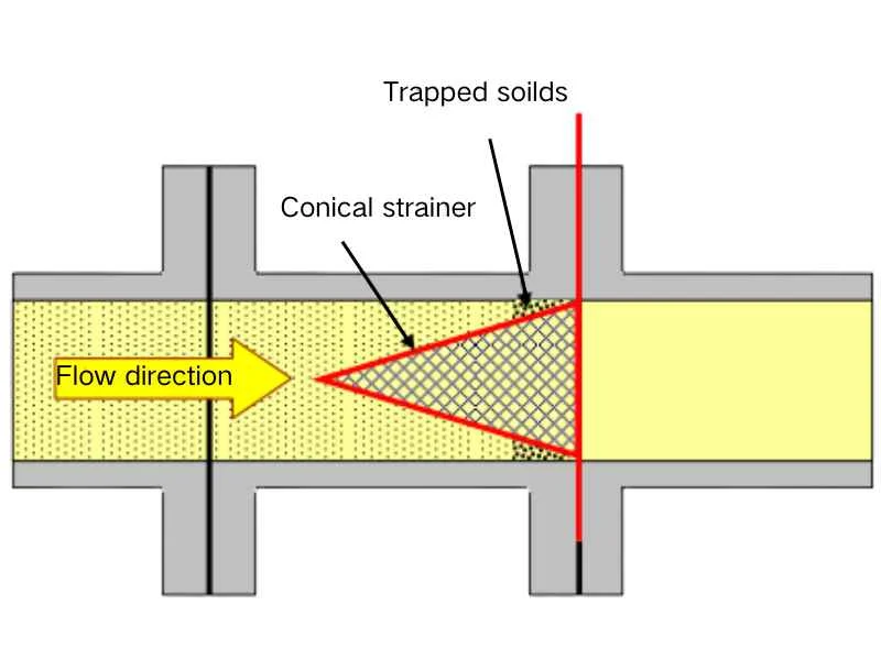
The cone strainer is clamped between two pipe flanges. Fluid passes through the perforated or mesh-lined cone while solid particles remain on its upstream surface.
- The cone strainer is installed before flushing or startup.
- Unfiltered fluid enters the open side of the element.
- Debris is retained by the perforations or wire mesh.
- Filtered fluid continues through the pipeline.
- Differential pressure rises as debris accumulates.
- The cone is removed after its defined temporary duty.
Debris Quantity
Determines the required filtration area and inspection frequency.
Screen Opening
Must protect equipment while allowing the required startup flow.
Pression différentielle
The cone must resist the specified clean and blocked conditions.
Available Pipe Length
The complete cone must fit inside the adjacent pipe section.
Technical Options
Cone Strainer Configuration Guide
Available options depend on pipeline dimensions, process conditions and the commissioning procedure.
| Paramètres | Typical Options | Information Required |
|---|---|---|
| Cone Shape | Pointed, truncated or reverse cone | Available length and flow direction |
| Flange Ring | Raised-face, full-face or ring-joint compatible | Flange standard, class and facing |
| Screen Construction | Perforated plate, wire mesh or combined construction | Particle size and required strength |
| Element Material | Carbon steel, SS304, SS316 or project-specified alloy | Fluid compatibility and corrosion conditions |
| Filtration Direction | Inside-to-outside or outside-to-inside | Flow direction and pressure loading |
| Reinforcement | Standard ribs, rings or heavy-duty support | Maximum differential pressure |
| Identification Handle | Plain, stamped or tagged | Site identification requirement |
| Documentation | Drawing, material record and inspection report | Agreed project scope |
Screen Selection
Opening Size and Effective Filtration Area
Cone strainer design should balance debris retention, open area, strength and allowable startup pressure drop.
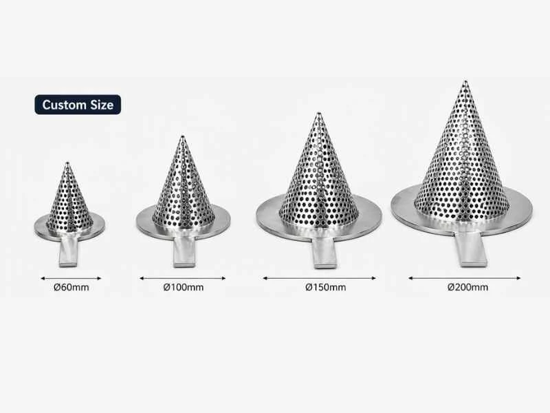
Element Construction Options
- Perforated plate for coarse debris
- Woven mesh for smaller particles
- Mesh supported by perforated plate
- Single-layer or multi-layer construction
- Reinforced element for higher differential pressure
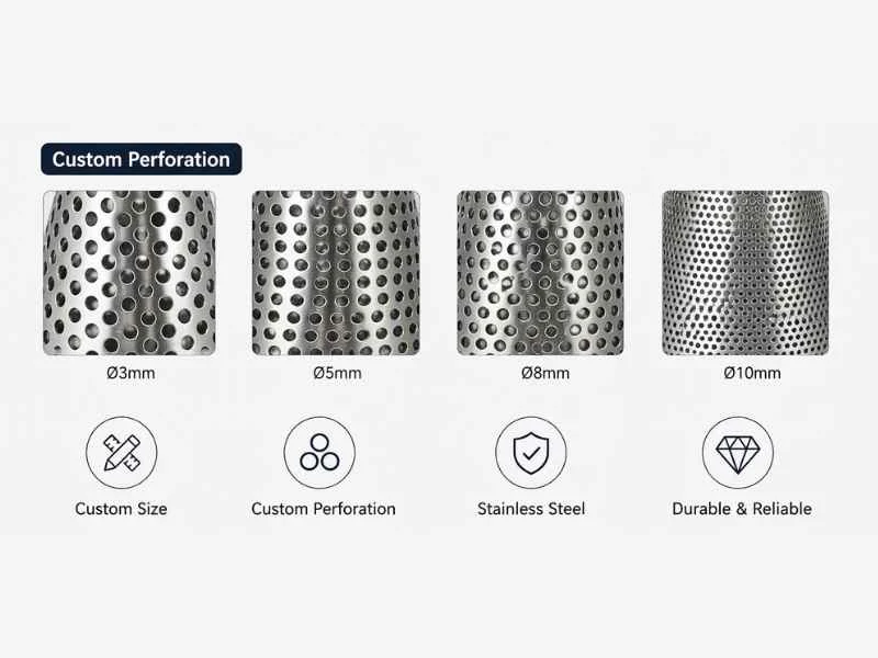
Selection Considerations
- Smallest debris that could damage downstream equipment
- Expected amount and type of construction debris
- Required flushing and startup flow rate
- Maximum allowable pressure drop
- Available cone length and pipe clearance
| Screen Type | Filtration Characteristic | Relative Strength | Utilisation typique |
|---|---|---|---|
| Perforated Plate | Coarse filtration | Haut | Weld slag, rust and scale |
| Mesh-Lined Plate | Medium or fine filtration | Supported | Pumps, valves and meters |
| Multi-Layer Element | Project-specific filtration | Design dependent | Special commissioning requirements |
| Reinforced Element | Coarse or fine filtration | Very high | Higher differential-pressure conditions |
Size Reference
Pointed Cone Strainer Dimensions
Selected metric catalog dimensions are provided for preliminary planning. Confirm the approved drawing before fabrication or installation.
| Nominal Size | Flange Outside Reference | Cone Diameter | Cone Height | Plate Thickness |
|---|---|---|---|---|
| DN25 | 62-70 mm | 26 mm | 90 mm | 2 mm |
| DN50 | 94-105 mm | 55 mm | 130 mm | 2 mm |
| DN80 | 132-142 mm | 92 mm | 150 mm | 2 mm |
| DN100 | 152-162 mm | 113 mm | 160 mm | 2 mm |
| DN150 | 206-218 mm | 172 mm | 210 mm | 3 mm |
| DN200 | 262-282 mm | 242 mm | 240 mm | 3 mm |
| DN300 | 370-395 mm | 363 mm | 300 mm | 3 mm |
| DN400 | 470-510 mm | 479 mm | 365 mm | 6 mm |
| DN500 | 575-616 mm | 600 mm | 430 mm | 6 mm |
| DN600 | 676-726 mm | 714 mm | 490 mm | 6 mm |
Dimensions vary with pressure class, flange standard, element orientation and reinforcement design. Final dimensions must follow the approved project drawing.
Matériaux
Material Options for Pipeline Conditions
Plate, mesh, reinforcement and flange-ring materials should be selected according to the medium, temperature, corrosion risk and startup duration.
| Composant | Typical Material Options |
|---|---|
| Perforated Cone | Carbon steel, SS304, SS304L, SS316 or SS316L |
| Wire Mesh | SS304, SS304L, SS316 or SS316L |
| Reinforcement | Material compatible with the cone element |
| Flange Ring | Carbon steel or stainless steel |
| Identification Handle | Carbon steel or stainless steel |
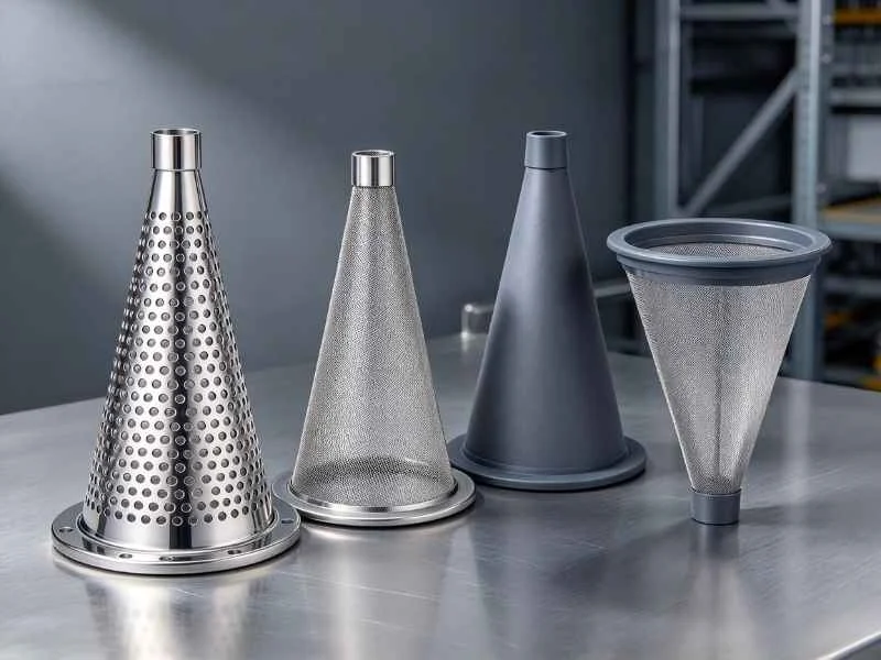
Selection Checklist
Information Required for Cone Strainer Selection
Complete startup and pipeline data allows the manufacturer to review cone shape, filtration area, strength and installation dimensions.
Process Data
- Flushing or process medium
- Design pressure and temperature
- Startup pressure and temperature
- Normal and maximum flow rates
- Expected installation duration
Filtration Data
- Required perforation or mesh size
- Expected debris type and quantity
- Perte de charge admissible
- Required filtration-area ratio
- Maximum differential pressure
Piping Data
- Nominal pipe size
- Flange standard and pressure class
- Flange facing and gasket dimensions
- Available internal pipe length
- Flow direction and cone orientation
Applications
Cone Strainer Applications
Cone strainers protect newly installed or serviced equipment during flushing, commissioning and initial operation.
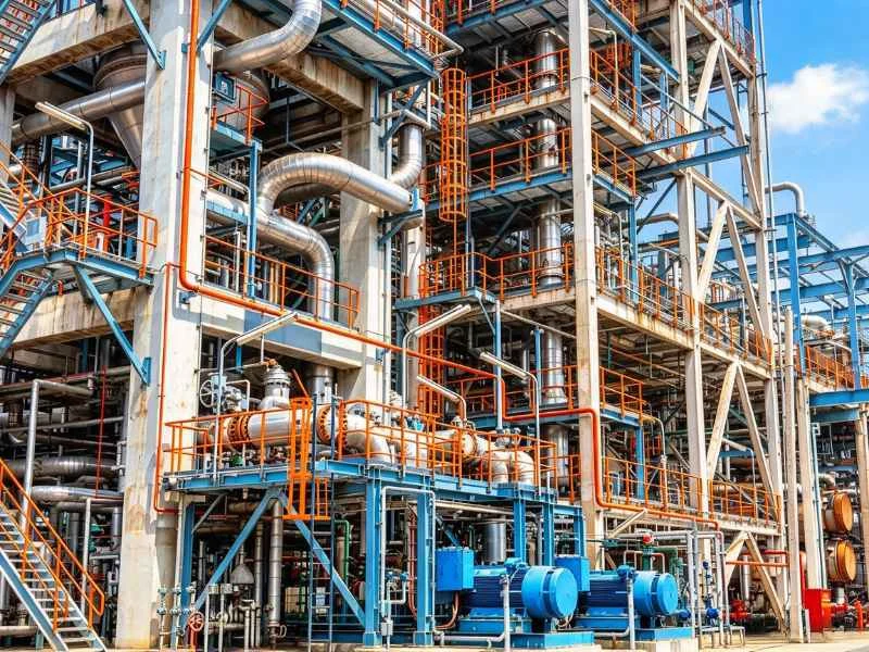
Pétrole et gaz
Startup protection for pumps, compressors, meters and process equipment.

Traitement chimique
Commissioning filtration for chemical and process-fluid pipelines.

Production d'électricité
Debris protection during flushing of steam, water and auxiliary systems.
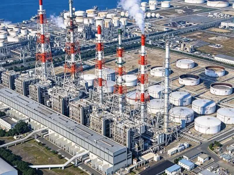
Raffineries
Initial pipeline protection for refinery units and transfer systems.
Manufacturer Quality Control
Inspection Before Delivery
The inspection scope depends on the selected cone strainer construction and agreed project requirements.
- Review the approved datasheet and fabrication drawing.
- Verify plate, mesh, reinforcement and flange-ring materials.
- Inspect element diameter, height and flange dimensions.
- Check perforation or mesh opening size.
- Inspect welding, reinforcement and identification markings.
- Review cleanliness, documentation and protective packing.
Installation & Removal
Use Cone Strainers Safely
The commissioning plan should define element orientation, pressure monitoring, inspection frequency and final removal.
Installation Guidelines
- Verify pipeline flow direction before installation.
- Confirm the cone fits inside the adjacent pipe section.
- Install the element in the approved orientation.
- Use gaskets suitable for the flange and process conditions.
- Keep the identification handle visible outside the flanges.
- Provide upstream and downstream pressure monitoring.
Inspection and Removal
- Monitor differential pressure during flushing and startup.
- Reduce flow if pressure drop approaches the project limit.
- Depressurize and drain the pipeline before removal.
- Inspect the cone for deformation or damage.
- Remove the element after its defined temporary duty.
- Install the correct permanent gasket before closing the flanges.
Send Us Your Cone Strainer Data
Provide the pipe size, flange standard, startup flow, medium, screen opening, differential pressure and available pipe length. BCST Valve will recommend a suitable cone strainer.
Questions fréquemment posées
Cone Strainer FAQ
Answers to common questions from engineers, commissioning teams and procurement specialists.
What is a cone strainer?
A cone strainer is a temporary pipeline filter installed between flanges to capture construction debris during flushing, commissioning and startup.
Why use a cone instead of a flat strainer?
A cone generally provides more filtration area and dirt-holding capacity than a flat plate of the same pipe size.
What is a truncated cone strainer?
A truncated cone has a flat end and shorter overall length, making it useful where a full pointed cone will not fit inside the available pipe section.
Which direction should the cone point?
Orientation depends on flow direction, support construction and differential-pressure loading. Follow the approved product drawing.
How is the screen opening selected?
Select an opening small enough to protect downstream equipment while maintaining acceptable startup flow and pressure drop.
How is cone length determined?
Cone length depends on pipe size, required filtration area, cone angle, pressure-drop requirement and available internal pipe clearance.
How is blockage detected?
Pressure readings upstream and downstream of the cone indicate increasing differential pressure as debris accumulates.
Can a cone strainer remain permanently installed?
It should normally be removed after its defined duty unless the pipeline and element have been specifically reviewed for continued operation.
Can BCST Valve manufacture custom cone strainers?
Project-specific flange rings, cone lengths, materials, screen openings and reinforcement designs can be reviewed against submitted pipeline data.
What information is required for a quotation?
Provide the pipe size, flange details, pressure, temperature, medium, flow rate, screen opening, differential pressure and available installation length.
Need Help Selecting a Cone Strainer?
Send your pipeline and commissioning data to BCST Valve for technical selection and quotation support.
 English
 Arabic
 Russian
 French
 Spanish