
Butterfly Valve Symbol: P&ID Meaning, Types, and Standards
Are you confused by P&ID symbols? Misreading them can cause huge project delays and safety risks. Let’s make sure you understand them correctly every single time.
Le butterfly valve symbol on a P&ID diagram looks like two triangles with their points touching. A line runs through the center where they meet. This symbol shows a valve with a rotating disc for flow control. It is very important for engineers to read it correctly.
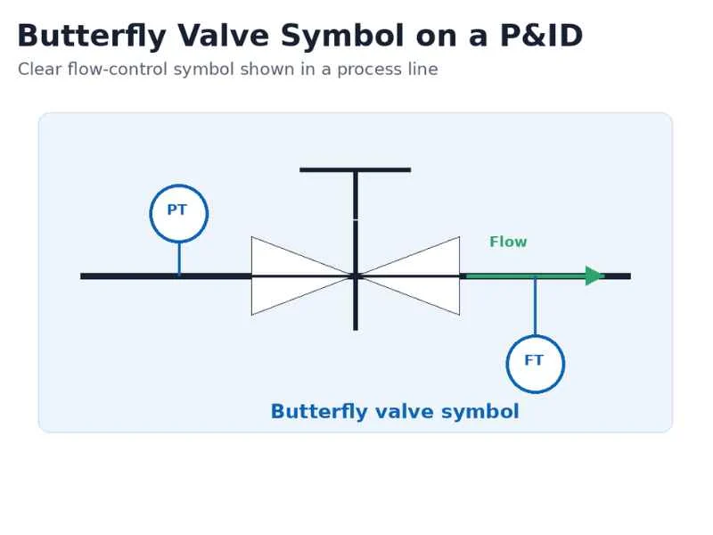
This simple symbol holds a lot of information. For an experienced engineer like Hassan, a project chief engineer I know, understanding every detail of this symbol is crucial. It ensures the whole plant design is safe and efficient. This symbol is not just a drawing; it is a command that tells you what part to use and how it works in the system. Getting it right prevents costly mistakes and keeps the project on schedule. Let’s look closer at why this symbol is so important for your projects and how to read it like an expert.
The Basic Butterfly Valve Symbol Explained
Do P&ID diagrams feel like a secret code? A single wrong symbol can mess up your entire design. You need a clear guide to understand them perfectly and avoid confusion.
The standard butterfly valve symbol is two triangles joined at their tips. A straight line passes through the center. This represents the valve body and the internal disc. Sometimes, a T-shaped handle on top shows it is a manual valve.
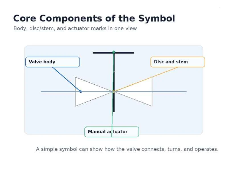
The Core Components of the Symbol
Le butterfly valve symbol is simple, but each part has a meaning. The two triangles represent the valve body. They show where the valve connects to the pipe. The line in the middle represents the disc. This is the part that turns to control the flow of liquid or gas. On top of the symbol, you might see another small drawing. This indicates the actuator, which is the device that opens or closes the valve. Understanding these three parts—body, disc, and actuator—is the first step. It helps you see how the valve works just by looking at the P&ID. This basic knowledge is essential for everyone on a project, from the designers to the technicians who install the equipment. It ensures everyone speaks the same visual language.
| Symbol Part | What it Represents | Why it’s Important |
|---|---|---|
| Two Triangles | Le corps de la valve | Shows where the valve fits in the pipeline. |
| Center Line | The disc and stem | Indicates the mechanism that controls the flow. |
| Actuator Symbol | How it’s operated | Tells you if it’s manual, pneumatic, or electric. |
Reading the Flow Direction
A common question is whether the symbol shows the flow direction. The basic symbol for a butterfly valve is bi-directional. This means it can handle flow in either direction. So, the symbol itself does not tell you which way the fluid is moving. To find the flow direction, you must look for other clues on the P&ID. The most important clue is the arrowhead drawn on the pipeline itself. This arrowhead is the official indicator of flow direction for the entire line. Following this arrow is critical. For some high-performance butterfly valves, the manufacturer may recommend a preferred flow direction for best performance. In these cases, an arrow might be on the valve body itself, and it should be installed accordingly.
Distinguishing Butterfly Valve Symbols from Other Valve Types
Have you ever mistaken a gate valve for a butterfly valve on a complex diagram? This common error can lead to ordering the wrong parts. It costs you time and money.
A butterfly valve symbol (two touching triangles) is very different from a gate valve symbol (two triangles with a vertical line between them). A ball valve is shown with a solid circle inside the triangles. And a globe valve uses a filled-in black circle between the triangles.
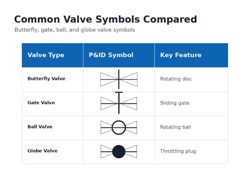
Key Visual Differences
Recognizing different valve symbols is a fundamental skill. Each symbol provides a quick visual cue about the valve’s internal mechanism. The butterfly valve’s touching triangles show a rotating disc. The gate valve’s symbol, with its separating line, represents a gate that moves up and down. For a ball valve, the circle in the middle clearly indicates a ball with a hole through it. And the globe valve’s filled-in circle represents the plug that lowers onto a seat to control flow. Learning these differences is like learning the alphabet of P&IDs. It allows you to quickly understand the function of each component in a process line without needing to read detailed notes every time. This speed and accuracy are vital in design reviews and during plant operations.
| Type de vanne | Symbol Description | Key Feature |
|---|---|---|
| Vanne papillon | Two triangles touching at the points. | Represents a rotating disc for quick shut-off. |
| Vanne à guillotine | Two triangles with a vertical line between them. | Shows a sliding gate for on/off control. |
| Soupape à bille | Two triangles with an open circle in the middle. | Indicates a rotating ball for quick shut-off. |
| Robinet à soupape | Two triangles with a filled black circle in the middle. | Represents a plug for precise flow control (throttling). |
Why the Difference Matters for Design
Choosing the right valve is not just about the symbol; it is about function. The symbol tells the engineer what type of valve to use, and this choice has a big impact on the plant’s performance. For example, Hassan’s team would specify butterfly valves for cooling water systems. They are great for quick shut-off, they are compact, and they work well for throttling. However, for a main process pipeline where an uninterrupted flow is critical, they would choose a gate valve because it has a very low pressure drop when fully open. A globe valve would be the choice for a line where precise flow control is needed, like controlling the steam to a heater. The ball valve is another excellent choice for quick on/off isolation. Each symbol corresponds to a specific function, and selecting the correct one is key to an efficient and safe plant design.
Understanding Actuator Symbols on Vannes papillon
You see a symbol on top of the valve, but what does it mean? Not knowing if it is manual or automated can ruin your control strategy. Let’s fix that now.
Actuator symbols are drawn above the main butterfly valve symbol. A simple ‘T’ handle indicates manual operation. A circle with letters inside shows automated control. For example, ‘P’ is for pneumatic and ‘E’ is for electric. This tells you how the valve is opened and closed.
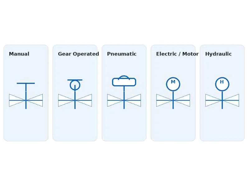
Common Actuator Notations
The actuator symbol tells you how the valve is powered. A simple ‘T’ or ‘L’ shape above the valve means it has a manual handle or lever. If you see a circle on top of that ‘T’, it means it has a manual gearbox, used for larger valves that need more force to turn. For automated valves, the symbols are different. A circle with a semicircle on top or the letter ‘P’ inside means it is a pneumatic actuator, powered by compressed air. This is very common for fast-acting valves. A circle with an ‘M’ or ‘E’ inside signifies an electric motor actuator. These are used for precise positioning and remote control. Knowing these notations helps you understand the level of automation in the plant.
| Type d'actionneur | Common Symbol/Letter | Typical Application |
|---|---|---|
| Manual (Lever/Wrench) | ‘T’ or ‘L’ shape | Simple on/off, local control. |
| Manual (Gear Operated) | Circle on top of ‘T’ | For larger valves needing more torque. |
| Pneumatique | Circle with a line/semicircle on top; or ‘P’ | Fast-acting automated control, common in plants. |
| Electric/Motor | Circle with an ‘M’ or ‘E’ inside | Precise positioning, remote control systems (DCS). |
| Hydraulique | Circle with an ‘H’ inside | High-torque applications requiring strong force. |
Linking Actuators to Control Philosophy
The choice of actuator is a critical part of the plant’s overall control strategy. It is not a random decision. For an emergency shutdown (ESD) system, an engineer would likely choose a pneumatically actuated butterfly valve. Why? Because it can close very quickly in an emergency. It would also be specified as “fail-close,” meaning if the air supply is lost, a spring will automatically shut the valve for safety. In contrast, a valve used to control the temperature of a product might use an electric motor actuator. This allows for very precise, small adjustments to the valve position from a central control room. Hassan’s engineering team spends a lot of time defining this control philosophy. They decide which valves need to be automated, how they should operate, and what their fail-safe position should be. This ensures the plant runs smoothly, efficiently, and most importantly, safely.
How P&ID Standards Define the Butterfly Valve Symbol
Are your P&IDs consistent across projects? Using different standards can create chaos and misunderstanding between teams. This is a risk you cannot afford to take in any project.
Different standards like ISA (International Society of Automation) and ISO (International Organization for Standardization) define the butterfly valve symbol. While the basic shape is similar, there can be small variations. Always check your project’s specified standard to ensure everyone is on the same page.
A Look at ISA S5.1
In many parts of the world, especially in North America, the ISA S5.1 standard is the guide for instrumentation symbols. This standard provides a complete library of symbols for P&IDs, ensuring that everyone designs and reads them the same way. According to ISA S5.1, the butterfly valve is represented by the familiar two triangles meeting at their points. The standard also provides ways to add more detail. For example, notes next to the symbol can specify if it is a wafer, lug, or flanged type. A project manager like Hassan insists on using one single standard for a project. This eliminates any confusion between the design office, the procurement team buying the valves, and the construction crew installing them. Using a clear standard like ISA S5.1 prevents mistakes, saves money, and makes the project safer.
Comparing with ISO 10628
For international projects, you will often encounter the ISO 10628 standard. This is another major set of rules for creating diagrams for the process industry. The good news is that for basic symbols, ISO and ISA are very similar. The butterfly valve symbol in ISO 10628 is also two triangles touching at their points. This consistency is very helpful for global companies and engineers working on international teams. However, there can be small differences in how more complex information is shown, like for actuators or special valve features. The most important lesson here is to define the standard at the very beginning of the project. My father, who started our valve factory, always said, “Clarity on paper saves money in the field.” This is especially true for P&IDs. Everyone on the project must know which standard to follow, and they must stick to it.
Frequently Asked Questions (FAQ)
Q: What is the most common butterfly valve symbol on a P&ID?
A: The most common butterfly valve symbol is two triangles with their tips touching. A line runs through the center to represent the disc. This basic symbol is recognized by most engineering standards, like ISA S5.1, making it universally understood in the industry.
Q: How do you show an actuated butterfly valve symbol?
A: You add an actuator symbol above the basic butterfly valve symbol. For example, a ‘T’ handle indicates a manual valve. A circle with a semicircle on top or the letter ‘P’ indicates a pneumatic actuator, showing it’s automated with compressed air.
Q: What’s the difference between a butterfly valve symbol and a gate valve symbol?
A: A butterfly valve symbol has two triangles touching at the points. A gate valve symbol has two triangles separated by a vertical line in the middle. This small difference represents two very different valve functions and internal mechanisms.
Q: Does the butterfly valve symbol indicate the connection type, like wafer or lug?
A: The basic symbol does not usually show the connection type. This important information is typically provided in the P&ID line list, the detailed valve specifications sheet, or with a text note written next to the symbol itself on the diagram.
Q: Why is it important to standardize the butterfly valve symbol in a project?
A: Standardizing the symbol ensures everyone—from design engineers to procurement specialists and construction teams—reads the diagram the same way. This prevents errors, avoids ordering the wrong parts, and improves overall project safety, quality, and efficiency.
Q: Can the butterfly valve symbol show if the valve is normally open or normally closed?
A: Yes. Often, text like ‘NO’ (Normally Open) or ‘NC’ (Normally Closed) is written near the symbol. For automated valves, the fail position (Fail Open ‘FO’ or Fail Close ‘FC’) is also noted to define its safety function during a power or air loss.
Dernière réflexion
Correctly reading the butterfly valve symbol is essential for project success. We’ve covered its basic form, actuator types, and how standards ensure clarity. For your valve needs, from standard units to automated solutions, BCST provides the expertise and quality to support your project. Contact us for reliable solutions.



 English
 Arabic
 Russian
 French
 Spanish