
You’ve meticulously designed your mold, selected the right material, and dialed in your injection molding machine. Yet, there they are – frustrating sink marks or hidden voids marring the surface of your thick-walled plastic parts. These common injection molding defects not only ruin aesthetics but can compromise structural integrity, leading to costly rejects and rework. If you’re battling these issues, you know that controlling pressure during the pack and hold phase is critical. But are you using the right tools for the job? This article explores how advanced pressure control using proportional relief valves is a game-changer to prevent sink marks in injection molding, especially in challenging thick-section geometries. We’ll dive deep into why sink marks happen and how precise pack pressure optimization offers a powerful solution.
Why Sink Marks and Voids Plague Thick Parts
Before we can effectively prevent sink marks in injection molding, we need to understand their origin.
- Sink Marks: These are surface depressions or dimples that typically occur in thicker sections of a molded part, often opposite ribs or bosses.
- Voids: These are internal bubbles or cavities within the part, often invisible from the surface but detrimental to strength and performance.
Both defects stem from the same root cause: volumetric shrinkage. As molten plastic cools and solidifies within the mold cavity, it naturally shrinks.
- Differential Cooling: In thick-walled parts, the outer surface cools and solidifies faster against the relatively cooler mold walls. The core material, however, stays molten longer. As this core material finally cools and shrinks, it pulls the still-soft surface material inwards, creating a sink mark. If the outer skin is already too rigid, the shrinking core creates an internal void instead.
- Insufficient Compensation: If pressure isn’t adequately maintained during this cooling and shrinkage phase (the pack and hold stage), there isn’t enough force to push additional molten material into the cavity to compensate for the volume loss.
Thick sections exacerbate this because they require significantly more cooling time, allowing greater potential for shrinkage and making uniform pressure transmission difficult. The consequences go beyond appearance – sink marks and voids can lead to part failure, customer dissatisfaction, and increased production costs. Understanding the causes of sink marks injection molding is the first step toward eliminating them.
The Critical Role of Pack and Hold Pressure
The injection molding cycle consists of several key stages: Filling, Packing, Holding, Cooling, and Ejection. The Pack and Hold phases are absolutely vital for part quality, particularly to prevent sink marks in injection molding.
- Packing Phase: After the mold cavity is mostly filled (around 95-99%), the machine transitions from filling speed control to pressure control. Packing pressure forces additional material into the cavity to compensate for initial shrinkage as the plastic begins to cool.
- Holding Phase: This phase maintains pressure on the material as it continues to cool and solidify, crucially keeping pressure applied until the gate (the entry point into the cavity) freezes or seals. This prevents material from flowing back out of the cavity and ensures continued compensation for shrinkage.
Why Basic Systems Fall Short: Traditional injection molding setups might use simple pressure relief valves with fixed settings or basic on/off control. This often isn’t precise enough for demanding applications:
- Fixed Pressure Limits: Doesn’t allow for dynamic adjustments needed during the pack/hold phase.
- Abrupt Changes: Can cause pressure spikes or drops, hindering smooth compensation.
- Difficulty Profiling: Implementing multi-stage pressure profiles (often ideal for thick parts) is difficult or impossible.
This lack of fine control during the critical pack and hold stage is a major contributor to defects like sink marks and voids. Effective injection molding pressure control requires more sophistication.
The Solution: Proportional Relief Valves in Injection Molding
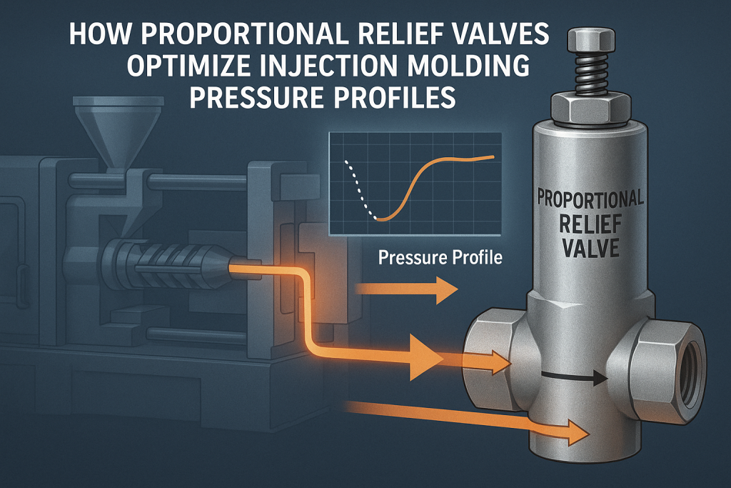
This is where proportional relief valve injection molding technology shines. Unlike standard relief valves that simply open fully at a set pressure, a proportional relief valve offers precise, electronically controlled pressure limiting.
How They Work: A proportional relief valve receives an electrical signal (typically voltage or current) from the machine’s controller. Based on this signal, an internal solenoid adjusts the position of a pilot poppet or spool, which in turn controls the main relief valve opening.
- Variable Control: A small input signal results in a low pressure limit; a large signal results in a high pressure limit. The key is that the pressure limit is proportional to the input signal.
- Dynamic Adjustment: The machine controller can change the signal in real-time, allowing the maximum system pressure (and thus the pack/hold pressure applied to the part) to be adjusted dynamically throughout the cycle.
This enables proportional valve pressure control with far greater accuracy and flexibility than traditional methods. It allows the machine to precisely follow complex pressure commands essential for defect prevention.
Optimizing Pack and Hold Pressure Profiles
Simply having a proportional relief valve isn’t enough; the real power lies in using it to implement an optimized pressure profile. Instead of a single pack/hold pressure setting, a profile involves multiple pressure steps or ramps over time during the pack and hold phase.

Why Profile? The shrinkage rate of plastic isn’t constant; it changes as the material cools. An optimal profile aims to match the pressure applied to the material’s needs as it solidifies:
- Initial High Pack Pressure: Quickly forces extra material into the cavity to compensate for the initial rapid shrinkage.
- Stepped Pressure Decay: Gradually reduces pressure as the material cools and shrinkage slows. This prevents overpacking (which can cause stress or flash) while still counteracting shrinkage effectively until the gate seals.
Implementing Profiles with Proportional Valves: Le proportional relief valve injection molding system allows the machine controller to precisely execute these multi-stage profiles. The controller sends varying signals to the valve, adjusting the pressure limit according to the programmed profile.
Table 1: Example Pack/Hold Pressure Profile Stages
| Stage | Pressure Level | Duration | Purpose | Enabled By |
|---|---|---|---|---|
| Pack 1 | High (e.g., 80% of Fill) | Short (e.g., 1s) | Rapidly compensate initial shrinkage | Soupape de décharge proportionnelle |
| Hold 1 | Medium (e.g., 60%) | Medium (e.g., 3s) | Continue compensation as outer layers solidify | Soupape de décharge proportionnelle |
| Hold 2 | Lower (e.g., 40%) | Until Gate Seal | Maintain pressure, prevent overpacking, avoid stress | Soupape de décharge proportionnelle |
| (Note: | Values are examples | and vary greatly | based on material, part geometry, etc.) |
Achieving the ideal pack pressure optimization injection molding profile often requires careful tuning based on material properties, part geometry, and mold characteristics. Monitoring actual cavity pressure with transducers provides invaluable feedback for this process.
Practical Steps to Prevent Sink Marks using Optimized Pressure
Implementing and tuning these profiles requires a methodical approach:
- Establish Baseline: Start with recommended pressure settings for your material or a conservative profile.
- Analyze Parts: Mold initial parts and carefully inspect for sink marks, voids, flash, and signs of stress.
- Iterative Adjustment:
- Sink Marks Present: Gradually increase pack/hold pressures or extend hold times. Focus on maintaining pressure until gate seal is confirmed (e.g., via a gate seal study).
- Flash or Overpacking: Reduce peak pack pressure or adjust the decay rate. Ensure clamp force is adequate.
- Internal Voids: Often requires higher, sustained holding pressure for longer durations.
- Monitor & Record: Use pressure transducer readings (if available) to correlate machine settings with actual cavity conditions. Keep detailed records of parameter changes and resulting part quality.
- Verify Gate Seal: Perform a gate seal study (molding parts with progressively longer hold times and weighing them) to ensure the hold phase is long enough.
Table 2: Troubleshooting Guide: Pressure Adjustments for Defects
| Defect Observed | Potential Pressure-Related Cause | Potential Proportional Valve Adjustment Strategy | Related Keywords |
|---|---|---|---|
| Sink Marks | Insufficient pack/hold pressure; Hold time too short | Increase pressure levels in profile; Extend hold duration | prevent sink marks injection molding |
| Internal Voids | Insufficient holding pressure; Premature gate seal | Increase holding pressure significantly; Ensure longer hold time | injection molding voids troubleshooting |
| Flash (Parting Line) | Excessive pack/hold pressure; Insufficient clamp force | Reduce peak pressure in profile; Check clamp tonnage | injection molding defects solutions |
| Warping/Stress | Overpacking (pressure too high or held too long) | Reduce pressure levels (especially later stages); Optimize decay | causes of sink marks injection molding (related) |
Remember, injection molding defects causes and solutions are often multi-faceted. While pressure profile optimization is powerful, it works best in conjunction with other good practices.
Beyond Pressure: Complementary Strategies
To effectively prevent sink marks in injection molding, consider these related factors:
- Part Design: Aim for uniform wall thickness wherever possible. Use gradual transitions between thick and thin sections. Core out thick areas if feasible.
- Mold Design: Ensure adequate gate size and location (often gating into the thickest section helps). Optimize cooling channel placement for uniform cooling. Proper venting is essential.
- Material Selection: Some materials shrink more than others. Consider lower-shrinkage grades if appropriate. Ensure material is properly dried.
- Process Parameters: Optimize melt temperature, injection speed, and mold temperature alongside pressure profiles.
Why Choose Advanced Pressure Control? Benefits Recap
Investing time and potentially technology (like high-quality proportional relief valves) for precise pressure control yields significant returns:
- Reduced Defects: Directly addresses sink marks and voids.
- Lower Scrap Rates: Fewer rejected parts mean less wasted material and machine time.
- Improved Part Quality: Consistent, high-integrity parts with better dimensional stability and appearance.
- Process Consistency: Enables repeatable results shot after shot, run after run.
- Potential for Optimization: May allow for cycle time reduction by precisely controlling hold time rather than relying on excessive cooling.
This focus on injection molding process optimization through accurate pressure management is a hallmark of modern, efficient molding operations.
Conclusion
Sink marks and voids, particularly in thick-walled components, are persistent challenges in plastic injection molding. They arise primarily from material shrinkage during cooling without adequate compensation. While basic machine controls struggle to provide the necessary finesse, optimizing the pack and hold pressure profile offers a direct and effective solution. Implementing these precise, multi-stage profiles is made possible by advanced proportional relief valve injection molding technology. By understanding the causes of defects and leveraging the dynamic pressure control capabilities of these valves, manufacturers can significantly improve part quality, reduce waste, and achieve more consistent production outcomes. Taking steps to prevent sink marks in injection molding through optimized pressure control is not just about fixing a problem; it’s about elevating your entire molding process.


 English
 Arabic
 Russian
 French
 Spanish