
Pneumatic Control Valve: The Ultimate Comprehensive Guide to Operation and Maintenance
In the intricate dance of industrial automation, compressed air acts as a silent, powerful workhorse, but it’s the vanne de contrôle pneumatique that truly serves as the “brain,” orchestrating precise movements and fluid management. According to Cognitive market research, Globally, the broader pneumatic ball valve market sees North America holding over 40% share with 3.2% CAGR to 2031, Asia Pacific at 23% with 7.0% CAGR, and Europe at 30% with 3.5% CAGR. Growth factors include industrial automation, energy efficiency, and demand in oil & gas and water treatment
A vanne de contrôle pneumatique is an instrument that uses instrument air pressure to modulate or divert the flow of a process fluid. This comprehensive guide aims to demystify these critical components, providing engineers, technicians, and industrial professionals with a deep understanding of their mechanics, essential components, various types, and vital maintenance procedures. By the end, you’ll grasp not only how they work but also how to calibrate and troubleshoot them for optimal performance and unwavering safety.
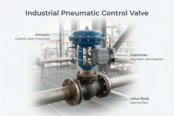
What is a Pneumatic Control Valve?
At its core, a vanne de contrôle pneumatique is a final control element in an automated system, designed to regulate process variables like flow, pressure, temperature, or liquid level. It achieves this by precisely adjusting the opening size of the flow passage in response to a pneumatic signal, typically from a controller.
Purpose in Process Automation: Regulating Flow, Pressure, and Temperature
In process automation, the ability to maintain stable conditions is paramount. Pneumatic control valves excel at this by providing continuous modulation. For instance, in a heat exchanger, a pneumatic valve might adjust the flow of steam to maintain a precise outlet temperature of a product. In a pipeline, it can throttle flow to ensure consistent pressure downstream, acting as a sophisticated pneumatic flow control valve. Their purpose is to directly influence the physical process based on feedback from sensors and commands from a control system, ensuring stable and efficient operations.
Why Choose Pneumatic over Electric? Speed, Fail-Safe Reliability, and Explosion-Proof Nature
While electric actuators are common, pneumatic control valves hold distinct advantages in many industrial contexts:
- Vitesse : Pneumatic actuators can deliver rapid, high-force movements, making them ideal for applications requiring quick response times, such as emergency shutdowns.
- Fail-Safe Reliability: They offer inherent fail-safe capabilities. Without power, a pneumatic valve can be designed to automatically move to a fully open or fully closed position (e.g., Fail-Open (FO) vs. Fail-Closed (FC)), ensuring safety during power outages or system failures.
- Explosion-Proof Nature: Since they operate on air pressure rather than electricity, pneumatic systems are intrinsically safe for use in hazardous, explosive environments, eliminating the risk of electrical sparks or static discharge that could ignite flammable gases or dust. This is a critical advantage in petrochemical and fuel industries.
- Robustesse : They are typically less susceptible to dust, moisture, and extreme temperatures compared to electrically driven valves.
How Does a Pneumatic Control Valve Work?
Understanding the operational mechanics of a vanne de contrôle pneumatique is key to appreciating its precision and reliability. The process typically involves a sophisticated control loop that translates a desired setpoint into a physical valve movement.
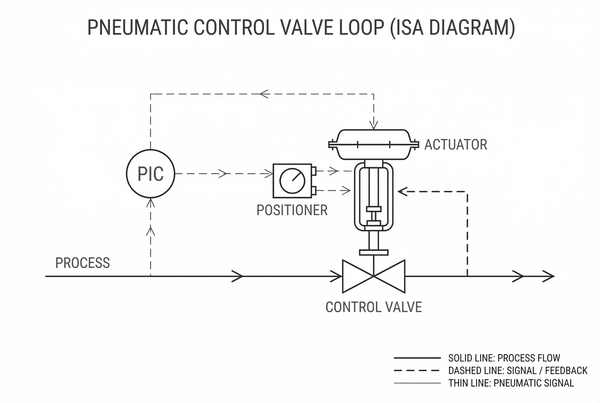
The Control Loop Basics: Controller → Positioner → Actuator
The operation of a vanne de contrôle pneumatique is a classic example of a closed control loop:
- Controller: This is the “brain” of the operation. It receives input from a sensor (e.g., temperature, pressure, flow rate), compares it to a desired setpoint, and calculates an output signal. This output is often an electrical signal (e.g., 4-20mA DC) for digital systems.
- Positioner (I/P Transducer): For pneumatic valves, this electrical signal from the controller must be converted into a pneumatic signal. The positionneur (often including an I/P Transducer) performs this conversion, translating the electrical 4-20mA into a proportional air pressure signal. This signal is known as the signal pressure.
- Actionneur : The actuator is the “muscle” that converts the signal pressure into mechanical force. As the air pressure changes, it pushes against a diaphragm or piston, which in turn moves the valve stem.
The Mechanics of Air Pressure: How the Signal Pressure Overcomes Spring Tension
Most common pneumatic actuators use a diaphragm connected to a spring. The signal pressure from the positioner is applied to one side of the diaphragm. As this pressure increases, it pushes against the diaphragm with enough force to overcome the opposing spring tension. This movement directly translates to the valve stem, which then moves the plug within the valve body, adjusting the flow area.
Standard Signal Pressure
The industry standard for signal pressure typically ranges from 3–15 psi (pounds per square inch) or 0.2–1.0 bar. This range corresponds to a 0-100% stroke of the valve. For example, 3 psi might represent 0% valve opening, and 15 psi might represent 100% opening.
Fail-Safe Modes: Explaining Fail-Open (FO) vs. Fail-Closed (FC) Logic
A critical safety feature of pneumatic actuators is their fail-safe design, dictating the valve’s state upon loss of instrument air pressure or signal:
- Fail-Open (FO): In this configuration, if the air supply or signal is lost, the spring forces the valve to the fully open position. This is typically used for cooling water lines or pressure relief valves where maintaining flow is safer than shutting off.
- Fail-Closed (FC): Here, upon loss of air, the spring forces the valve to the fully closed position. This is common for steam lines, fuel lines, or chemical feed lines where shutting off the flow is the safest action in an emergency.
The choice between FO and FC is a critical safety decision made during system design and must align with the process’s specific hazard analysis.
Which Components are Combined Within a Pneumatic Flow Control Valve?
A complete pneumatic flow control valve system is an assembly of several specialized components, each playing a crucial role in its overall function. Understanding these parts is essential for proper selection, installation, and maintenance.
The Actuator: The “Muscle” (Diaphragm or Piston)
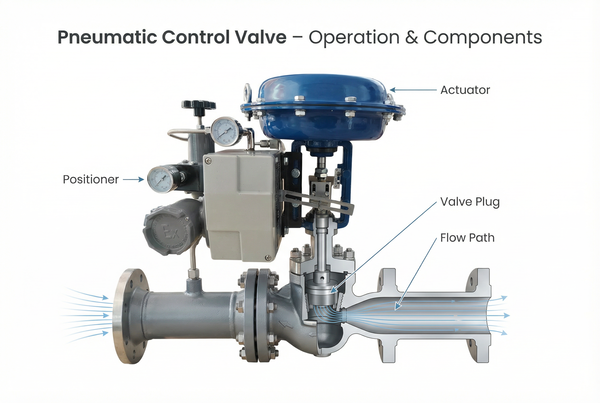
Le actionneur is the component responsible for converting the pneumatic signal pressure into mechanical motion to operate the valve. The two primary types are:
- Diaphragm Actuators: Most common for modulating control, offering precise and repeatable stroking. Air pressure acts on a flexible diaphragm, moving the stem against a spring.
- Piston Actuators: Used for higher thrust requirements and longer strokes. Air pressure acts on a rigid piston. They can be double-acting (air on both sides for precise control) or single-acting (spring-return).
The Valve Body and Trim: Where the Fluid Meets the Hardware (Plug, Seat, Stem)
Le valve body is the housing that contains the internal components and connects to the piping. The valve trim refers to the internal elements that come into direct contact with the process fluid and influence the flow characteristic. Key trim components include:
- Plug (or Disc): The movable element that controls the flow area. Its shape (e.g., contoured, V-port) dictates the flow coefficient ($C_v$) and flow characteristic (e.g., linear, equal percentage).
- Siège : The stationary surface against which the plug seals to block or regulate flow.
- Tige : The rod that connects the actuator to the plug, transmitting the actuator’s motion to open or close the valve.
- Emballage : Seals around the stem to prevent process fluid leakage to the atmosphere.
The Positioner: The “Brain” that Ensures Precision Through Feedback
Le positionneur is arguably the most crucial accessory for modulating control valves. It receives the pneumatic or electrical control signal and delivers the necessary air pressure to the actuator to ensure the valve stem moves to a precise position, overcoming friction, process forces, and stem stuffing box pressure. Modern positioners provide feedback, comparing the actual stem position to the commanded position and adjusting air pressure to correct any deviation, thus ensuring accurate and stable control. This is particularly important for controlling complex changes in pneumatic speed control valve adjustment.
Accessory Components: Air Filter Regulators, Solenoids, and Limit Switches
Various accessories enhance the functionality and reliability of pneumatic control valve components:
- Air Filter Regulators (AFR): Ensures a clean, dry, and regulated supply of instrument air to the positioner and actuator, preventing contamination and damage.
- Solenoid Valve (Sol): Used for on/off applications or as a pilot valve for larger actuators. A électrovanne converts an electrical signal into a pneumatic signal to quickly open or close an air supply, enabling rapid shut-off or opening of the main valve (e.g., for pneumatic directional control valve operations).
- Limit Switches: Provide electrical feedback to the control system indicating specific valve positions (e.g., fully open, fully closed).
- Volume Boosters: Used with large actuators to rapidly fill or exhaust air, speeding up valve response.
Types of Pneumatic Control Valves
The versatility of pneumatic control valves stems from their varied designs, each optimized for specific flow management tasks.
Pneumatic Directional Control Valves: Managing the “Path” of Flow
Pneumatic directional control valves are primarily used to switch or direct the flow of fluid (or air, in pneumatic systems) to different paths. They often have multiple ports and positions, changing the direction of flow. Common examples include 2-way, 3-way, and 4-way valves. They are essential for activating cylinders, diverting flow in manifolds, or selecting different process lines.
Pneumatic Flow and Speed Control Valves: Managing the “Volume” and “Velocity”
These valves are designed to precisely regulate the volume of fluid flowing through a pipe (flow control) or the speed of an actuator (speed control). They typically achieve this by throttling the flow area, similar to how a faucet controls water flow. A pneumatic flow control valve might maintain a constant desired flow rate, irrespective of pressure fluctuations, while a pneumatic speed control valve adjustment tunes the exhaust or supply air from a cylinder to control its piston velocity.
2-Way vs. 3-Way Configurations
- 2-Way Valves: The simplest type, with one inlet and one outlet. They are used for on/off service or to modulate flow, either allowing or stopping fluid to pass through.
- 3-Way Valves: Feature three ports. They can be used for diverting flow from one inlet to either of two outlets, or for mixing fluids from two inlets into a single outlet. These are common in blending and bypass applications.
Maintenance: How to Calibrate and Adjust a Pneumatic Control Valve
Regular maintenance, including calibration and adjustment, is crucial for preserving the accuracy and reliability of vannes de contrôle pneumatiques, ensuring they perform within specified limits and avoid issues like oscillation or poor response time.
Steps to Calibrate for Precision: Zero and Span Adjustments
Calibration ensures that the valve’s full stroke accurately corresponds to the full range of the signal pressure (e.g., 3-15 psi). Here are the general steps for calibration of pneumatic control valves, often performed with the valve in the loop but isolated from process flow:
- Connect Calibration Equipment: Attach a precision pressure source and gauges to the positioner’s input and output, and a precise means to measure valve stem position.
- Zero Adjustment: Apply the minimum input signal pressure (e.g., 3 psi). Adjust the positioner’s “zero” or “start” setting until the valve stem reaches its minimum position (e.g., 0% open for FC, 100% open for FO).
- Span Adjustment: Apply the maximum input signal pressure (e.g., 15 psi). Adjust the positioner’s “span” or “end” setting until the valve stem reaches its maximum position (e.g., 100% open for FC, 0% open for FO).
- Linearity Check: Cycle the valve through several intermediate points (e.g., 25%, 50%, 75%) and verify that the stem position is proportional to the input signal. Adjust as needed.
- Confirm Fail-Safe: Verify the valve returns to its correct fail-safe position upon loss of instrument air.
Calibration Example (for Fail-Closed valve):
span
| Input Signal (psi) | Desired Valve Opening (%) | Measured Stem Position (%) | Correction |
|---|---|---|---|
| 3 | 0 | 0 (Adjust Zero) | Adjust ‘Zero’ screw |
| 6 | 25 | 25 (Monitor Linearity) | Fine-tune as needed |
| 9 | 50 | 50 (Monitor Linearity) | Fine-tune as needed |
| 12 | 75 | 75 (Monitor Linearity) | Fine-tune as needed |
| 15 | 100 | 100 (Adjust Span) | Adjust ‘Span’ screw |
How to Adjust Pneumatic Flow Control Valve Speed: Tuning the Exhaust or Supply Air
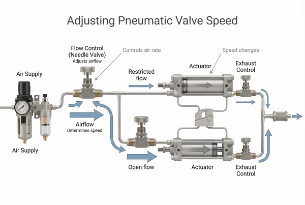
For applications specifically controlling the speed of a pneumatic actuator (e.g., a cylinder’s piston speed), adjustment is usually done by regulating the flow of air into or out of the actuator. This is typically achieved using:
- Needle Valves: Placed in series with the air supply or exhaust lines, these restrictors allow fine-tuning of air flow, directly affecting the speed of the actuator.
- Metering Devices: Some dedicated pneumatic speed control valve adjustment units have built-in orifices or restrictors that can be adjusted to control the velocity of the air flow to the actuator.
By controlling either the supply or exhaust air, the rate at which the actuator fills or empties air can be precisely managed, dictating the component’s operational speed.
Common Troubleshooting Issues: Air Leaks, Stiction, and Diaphragm Wear
Dépannage vannes de contrôle pneumatiques often involves addressing a few common issues:
- Air Leaks: The most frequent problem. Leaks in tubing, fittings, or actuator seals can lead to insufficient signal pressure, poor control, and wasted instrument air. Use soapy water to identify leak points.
- Stiction (Stick-Slip Friction): Occurs when the valve stem’s friction is too high, causing it to “stick” and then “jump” rather than moving smoothly. This results in poor control and hunting (oscillation). Causes include tight packing, stem corrosion, or insufficient positioner gain.
- Diaphragm Wear/Failure: The diaphragm in an actuator can crack or tear over time, especially with poor air quality or excessive cycling. This leads to loss of actuator force and inability to position the valve.
- Positioner Malfunction: Electronic or pneumatic components within the positioner can fail, leading to incorrect signal pressure output or loss of feedback.
Regular preventative maintenance, including lubrication of moving parts and inspection of air quality, can significantly mitigate these issues.
Frequently Asked Questions (FAQ)
Q: What is the standard signal pressure for pneumatic valves?
The industry standard for signal pressure, which defines the 0-100% stroke of a pneumatic control valve, is typically 3–15 psi (pounds per square inch) or 0.2–1.0 bar. This range is used by the positioner to translate an electrical control signal (e.g., 4-20mA) into a proportional air pressure for the actuator.
Q: What is the difference between a flow control et un directional control valve?
A pneumatic flow control valve primarily regulates the *volume* or *rate* of fluid (or air) passing through it, often by throttling the flow area, similar to a tap. A pneumatic directional control valve, on the other hand, manages the *path* or *direction* of flow, switching it between multiple outputs (e.g., extending or retracting a cylinder) but not necessarily controlling its speed or volume directly.
Q: Why is my pneumatic valve “hunting” or oscillating?
“Hunting” or oscillating in a vanne de contrôle pneumatique is usually a sign of instability in the control loop. Common causes include: incorrect tuning of the controller or positioner (e.g., too high gain), excessive friction or “stiction” in the valve stem, valve sizing issues (too large for the application), or inconsistent instrument air supply pressure. Addressing these underlying issues, often starting with positioner tuning and checking for mechanical friction, can resolve the oscillation.
Q: Can I use a pneumatic valve for steam applications?
Oui, vannes de contrôle pneumatiques are widely used for steam applications. However, specific considerations are crucial: the valve body and trim materials must be rated for high temperature and pressure, the packing must be suitable for steam service, and a properly sized and robust actuator is needed to handle the forces exerted by steam. Additionally, positioners and other pneumatic accessories often require isolation or cooling to protect them from the high temperatures of the steam.
Conclusion
Le vanne de contrôle pneumatique stands as a paragon of reliability and precision in industrial automation. From basic pneumatic flow control valve components to intricate calibration of pneumatic control valves, these devices are crucial for maintaining consistent process variables and ensuring operational safety in hazardous environments. Their inherent fail-safe capabilities and explosion-proof nature make them indispensable across a multitude of industries.
Mastering their operation, understanding their components (like the critical positionneur et actionneur), and diligently performing maintenance are not merely best practices—they are fundamental requirements for sustained efficiency and longevity in any fluid control system. By understanding the intricate mechanics of how does a pneumatic control valve work, industrial operators can ensure their systems run smoothly, minimizing downtime and maximizing output.
Need precision pneumatic control for your critical processes?


 English
 Arabic
 Russian
 French
 Spanish