

BCST: Manufacturer of Pressure Control Solution Valves
In the complex landscape of industrial processes, the precise management of pressure is not just a technical detail; it is a fundamental pillar of safety, operational efficiency, and system integrity. From safeguarding critical equipment against overpressure to maintaining optimal conditions for sensitive chemical reactions, effective pressure control solutions are indispensable.

Valves for Pressure Control Solution
: When specifying a Triple Offset Butterfly Valve, trust is paramount. Every BCST valve is built to exceed industry standards in our ISO 9001 certified factory. We hold crucial certifications including API 609, API 607 Fire Safe, and CE, guaranteeing our products are suitable for the most demanding services in oil & gas, chemical processing, and power generation. This commitment to certified quality is a core advantage of partnering with BCST.

Back Pressure Regulators
Lire la suite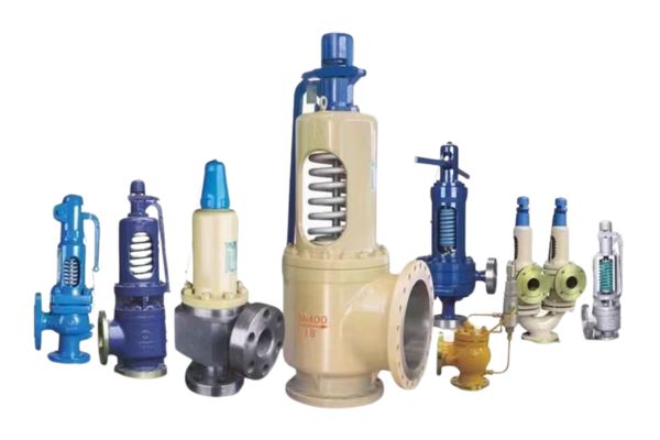
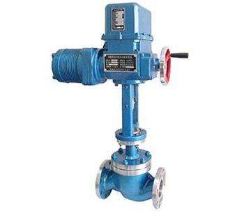
Pressure relief Valves
Vannes de régulation à soupape
Lire la suite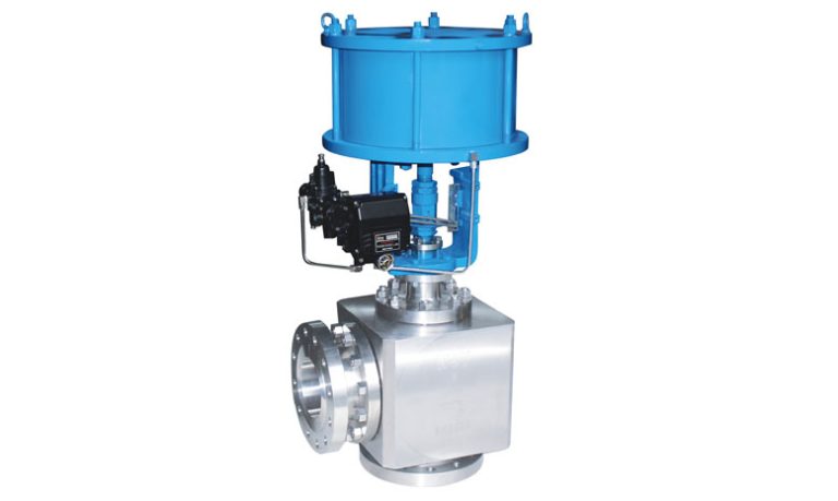
Angle Control Valves
Lire la suite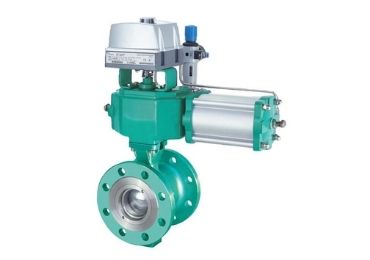
Segmented Ball Valve
Spécifications techniques et sélection
Des données techniques complètes et des outils interactifs pour vous aider à sélectionner la vanne idéale pour votre application.
Guide de sélection des matériaux
Choisissez le bon matériau pour votre application en fonction de la température, de la pression et de la compatibilité avec les fluides.
Réducteurs de pression
Self-operated valves designed to reduce higher upstream pressure to constant lower downstream pressure
Series:
BCST-PRV-3000
Pressure Range:
ASME Class 150 – 2500
Gamme de tailles :
1/2″ to 24″
Accuracy:
±1% of setpoint
Back Pressure Regulators
Maintain constant upstream pressure by controlling flow out of the system
Series:
BCST-BPR-4000
Pressure Range:
Up to 6000 psi
Température :
-196°C to +650°C
Temps de réponse :
< 1 second
Valve Types & Features
| Type de vanne | Operating Principle | Key Features | Applications |
|---|---|---|---|
| Direct-acting PRV | A ressort | Simple, reliable, low cost | Water systems and general services |
| Pilot-operated PRV | Pilot sensing | High precision, large capacity | Steam systems and process industries |
| Dome-loaded PRV | Gas pressure loaded | Precise control, remote operation | Chemical processing, oil and gas |
Données dimensionnelles
Tableau interactif des données dimensionnelles basé sur les normes GB/T 12221-2005.
Pressure Relief Valves
Safety devices that automatically open to discharge excess fluid or gas when system pressure exceeds setpoint
Series:
BCST-PRV-5000
Set Point Range:
15 to 6000 psi
Capacity:
Up to 1,000,000 lb/hr
Certifications:
ASME VIII, PED
Soupapes de sécurité
Used for compressible fluids (gases, vapors, steam) with quick opening characteristics
Series:
BCST-SV-6000
Blowdown:
2-7% of set pressure
Matériaux :
Carbon steel, stainless steel
Test :
100% tested
Relief Valve Specifications
| Paramètres | Standard PRV | Pilot Operated | Safety Valve |
|---|---|---|---|
| Set Point Accuracy | ±3% | ±1% | ±3% |
| Overpressure | 10% | 5% | 3% |
| Blowdown | 7-10% | 2-5% | 2-7% |
| Reseal Tightness | Bon | Excellent | Bon |
Transmetteurs de pression
Convert pressure readings into electrical signals for continuous monitoring and control
Series:
BCST-PT-7000
Accuracy:
±0.075% of span
Output:
4-20mA, HART, Foundation Fieldbus
Environmental Rating:
IP66/IP67
Pressure Switches
Simple on/off control devices that activate electrical contacts at specific pressure setpoints
Series:
BCST-PS-8000
Set Point Range:
0.5 to 6000 psi
Repeatability:
±0.5%
Electrical Rating:
250VAC, 10A
Transmetteurs de pression
Gauge Pressure
Measures pressure relative to atmospheric pressure • General industrial applications • Process monitoring • Pump discharge pressure
Absolute Pressure
Measures pressure relative to perfect vacuum • Weather monitoring • Altitude measurement • Vacuum processes
Pression différentielle
Measures difference between two pressure points • Flow measurement • Level measurement • Filter monitoring
Valve Types & Features
| Type de vanne | Operating Principle | Key Features | Applications |
|---|---|---|---|
| Direct-acting PRV | A ressort | Simple, reliable, low cost | Water systems, general service |
| Pilot-operated PRV | Pilot sensing | High precision, large capacity | Steam systems, process industries |
| Dome-loaded PRV | Gas pressure loaded | Precise control, remote operation | Chemical processing, oil & gas |
The BCST Factory Advantage: Advanced Pressure Control Solution Technology
Le cœur d'une vanne papillon à triple excentration (également connue sous le nom de vanne à triple excentration ou TOV) est sa conception innovante. BCST a perfectionné cette technologie dans son usine spécialisée. Les trois excentricités fonctionnent en harmonie : les deux premières placent le siège du disque hors du plan d'étanchéité, tandis que la troisième, un profil d'étanchéité conique unique, crée une fermeture à action de came et à siège de couple. Cette conception élimine le frottement entre le siège et le joint pendant le fonctionnement, ce qui prolonge considérablement la durée de vie de la vanne et garantit une fermeture étanche à la bulle, marque de fabrique d'un fabricant de premier plan.
Unmatched Precision
Advanced technology ensures exact regulation and stable maintenance of pressure within your systems
Operational Efficiency
Minimize energy consumption, reduce waste, and streamline processes with intelligent pressure management
Superior Safety
Multiple layers of safety features prevent overpressure and ensure system integrity
Robust Reliability
High-grade materials and rigorous testing ensure exceptional longevity and minimal maintenance
Tailored Solutions
Customizable pressure control systems seamlessly integrated into your existing infrastructure
Global Support
Extensive technical support, maintenance services, and training throughout the product lifecycle
Applications industrielles
Nos vannes papillon à triple excentrique excellent dans les secteurs industriels exigeants, offrant des performances fiables dans les environnements les plus difficiles.

Centrales électriques
Essentiel pour les systèmes de vapeur, de condensat et d'eau de refroidissement dans les centrales thermiques, nucléaires et à cycle combiné.

Industrie du pétrole et du gaz
Essentiel pour les systèmes de vapeur, de condensat et d'eau de refroidissement dans les centrales thermiques, nucléaires et à cycle combiné.
Traitement chimique
Manipulation de produits chimiques agressifs, de fluides de haute pureté et de boues avec une résistance chimique supérieure.
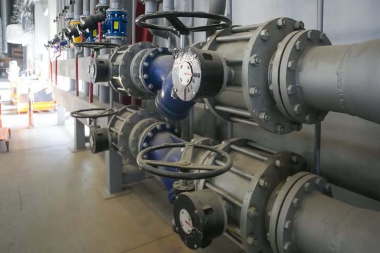
Traitement de l'eau
Pipelines de grand diamètre, stations de pompage et installations de traitement nécessitant une isolation et un contrôle du débit fiables.
L'avantage de l'usine BCST
En tant que fabricant direct, BCST contrôle l'ensemble du processus de production, ce qui lui confère des avantages significatifs en termes de qualité, de délais de livraison et de prix. Notre usine certifiée ISO 9001 garantit que chaque vanne répond aux normes les plus strictes.
- Prix directs d'usine
- Certifié ISO 9001
- Approuvé par API 609/607
- Équipe d'ingénieurs experts
56
Marques internationales
1000+
Des clients satisfaits
99.9%
Taux de qualité
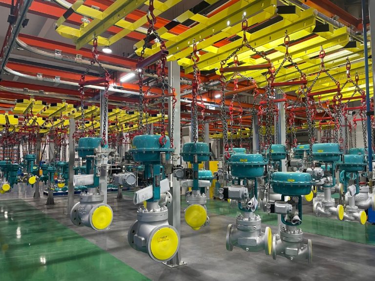
How Can You Master Pressure Control for Ultimate Safety and Efficiency?
Unstable pressure is a silent threat in your pipelines. It can trigger alarms, halt production, and even cause catastrophic equipment failure. This constant risk erodes profits, threatens safety, and complicates every aspect of your operation.
Mastering pressure control involves a systematic approach: selecting the correct final control element—either a regulator or a control valve—and pairing it with the right pressure instrumentation to create a stable, responsive, and safe system that protects your assets and optimizes performance.
From my earliest days watching my father build his valve business, I understood that pressure was the invisible force that drove everything. He used to say, “Pressure is like a powerful river. You can’t just dam it up; you have to build channels to guide its energy safely.” That lesson has been a cornerstone of my career. It was reinforced dramatically in a conversation I had with Hassan, a brilliant chief engineer responsible for designing entire petrochemical plants. He told me about a harrowing incident at a high-pressure polymerization reactor. A seemingly minor pressure fluctuation, caused by an improperly selected control device, led to an off-spec batch of product. The financial loss was over a quarter of a million dollars, but more importantly, it triggered a plant-wide safety review. Hassan explained that the root cause wasn’t a faulty valve but a misunderstanding of the system’s dynamic needs. This story illustrates a critical truth: effective pressure control isn’t just about individual components. It’s about designing a complete, intelligent system where every part works in harmony to tame that powerful river.
Regulator vs. Control Valve: Are You Using the Right Tool for the Job?
Are you specifying a complex, expensive control valve system for a simple pressure reduction task? Or worse, are you relying on a simple regulator for a dynamic process that demands precision, leading to instability and poor performance? This single choice can define your system’s reliability and cost.
A pressure regulator is a stand-alone mechanical device that automatically maintains a constant downstream pressure. A control valve is an actuated valve that modulates flow as part of a larger control loop, directed by an external controller to precisely manage dynamic process conditions.
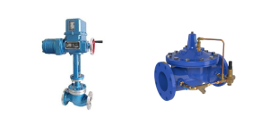
Choosing between a regulator and a control valve is one of the most fundamental decisions in fluid system design. The core difference lies in their intelligence and autonomy. A pressure regulator is the definition of “set and forget.” It’s a self-contained, mechanical marvel that uses the energy of the fluid itself to operate. You turn a screw to set your desired outlet pressure, and internal springs and diaphragms do all the work, automatically adjusting to changes in inlet pressure to hold the outlet steady. It’s like setting the cruise control in your car on a long, empty highway—it maintains a constant speed with no further input. This makes them perfect for steady-state applications, like supplying instrument air or reducing city water pressure to a building.
A control valve, however, is part of an intelligent team called a “control loop.” It doesn’t think for itself; it takes orders. The loop consists of:
- The Sensor (Pressure Transmitter): This is the “eyes” of the system, constantly measuring the process pressure.
- The Controller (PLC or DCS): This is the “brain,” comparing the transmitter’s reading to the desired setpoint and calculating the necessary correction.
- The Final Control Element (The Control Valve): This is the “hands,” receiving a signal from the brain and physically moving to adjust the flow.
This loop provides the dynamic responsiveness needed for complex processes where pressures must change based on reactions, temperatures, or flow rates—like the city driving to the regulator’s highway cruise control.
A critical, often overlooked, difference is their failure mode. Most regulators are designed to fail in the open position. A control valve system can be engineered to fail-safe. You can specify it to fail-open (e.g., for a cooling water line to prevent overheating), fail-closed (e.g., for a chemical injection line to prevent overdose), or fail-in-last-position to maintain the status quo during a signal loss. Hassan insists that analyzing the safest failure state is the first question his team answers when designing any critical control loop.
Direct-Operated vs. Pilot-Operated: Which Regulator Fits Your Flow?
Is your system experiencing frustrating pressure drops whenever demand increases? Your direct-operated regulator might not be able to handle the load, causing process instability and performance issues that a more advanced design could easily solve.
Use a direct-operated regulator for low-flow, stable applications where simplicity is key and minor pressure droop is acceptable. Choose a more sensitive pilot-operated regulator for high-flow, dynamic systems that demand tight, accurate pressure control.
Once you’ve decided a regulator is the right tool, you have another important choice to make. The difference between direct-operated and pilot-operated models is all about sensitivity and capacity.
A direct-operated pressure regulator is the essence of simplicity. It works on a straightforward force balance. A spring pushes down on a diaphragm, trying to open the valve, while the outlet pressure pushes up on the other side of the diaphragm, trying to close it. When the forces are balanced, the valve holds a steady position. This design is robust, inexpensive, and fantastic for simple, low-flow applications. Its primary weakness, however, is a phenomenon called “droop” or “offset.” As the flow demand increases, the valve has to open wider, which requires the spring to expand slightly. For the spring to expand, the balancing pressure from the outlet must decrease. Therefore, higher flow results in slightly lower pressure.
A pilot-operated regulator is a far more sophisticated, two-stage device designed to overcome this limitation. Think of it as a small, smart valve controlling a large, powerful one. A highly sensitive “pilot” stage senses the outlet pressure with extreme accuracy. Instead of trying to directly move the large main valve, this pilot uses the high inlet pressure as a power source, precisely directing it to open or close the main valve diaphragm. This hydraulic or pneumatic amplification means the pilot only has to do a tiny amount of work to control a massive amount of flow. The result is a regulator that can handle huge flow rates with incredible accuracy, maintaining a nearly flat pressure curve even as demand swings wildly. Hassan exclusively uses pilot-operated regulators for critical utilities like the main fuel gas feed to a plant’s power-generating turbines, where even a small pressure droop could affect power stability.
| Caractéristique | Direct-Operated Regulator | Pilot-Operated Regulator |
| Conception | Simple, single-stage, spring-balanced | Complex, two-stage, pressure-amplified |
| Précision | Good, but subject to pressure “droop” | Excellent, very little droop |
| Flow Capacity | Lower to moderate | Moderate to very high |
| Vitesse de réponse | Slower | Faster |
| Meilleur pour | Instrument air, point-of-use regulation, simple tasks | Main headers, high-demand systems, critical processes |
Control Valve Selection: How Do You Tame a Severe Service Application?
Is your control valve chattering, vibrating, or failing prematurely? Choosing a valve without considering the physics of your process fluid can lead to catastrophic damage from cavitation or flashing, rendering your entire control strategy useless and creating a severe safety hazard.
Proper control valve selection goes beyond sizing. It requires matching the valve’s characteristic to the process need, selecting robust materials, and, most critically, specifying a trim design that can withstand the destructive forces of cavitation and flashing.
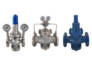
Selecting a control valve for a “severe service” application—one with high pressure drops or high temperatures—is a true engineering challenge. It’s where my discussions with Hassan always get deeply technical. While correct sizing (calculating the flow coefficient, Cv) is the first step, it’s just the ticket to entry. The real test is surviving the physics of the process.
The two biggest enemies are cavitation and flashing.
- Flashing: This occurs when a liquid enters the valve, and the pressure drop is so large that the pressure falls below its vapor pressure. The liquid boils and “flashes” into a vapor, and it remains a vapor as it exits the valve. This two-phase flow (liquid and gas) can be highly erosive, like a sandblaster.
- Cavitation: This is even more destructive. The liquid pressure drops below its vapor pressure, creating vapor bubbles, but then the pressure recovers downstream of the valve’s narrowest point (the vena contracta). This pressure recovery violently collapses the bubbles. This implosion creates incredible localized pressure spikes (up to 100,000 PSI) and microjets that act like tiny jackhammers, chipping away at the valve’s internals and downstream piping. The noise, vibration, and damage can be immense.
The solution lies in the heart of the valve: the trim. For these applications, a standard trim won’t survive. We must use specially engineered severe service trims:
- Anti-Cavitation Trim: This trim is designed to prevent the damaging collapse of bubbles. It often uses a multi-stage design, with a series of restrictive paths that force the pressure to drop in several small steps instead of one large one. This keeps the pressure from ever falling below the liquid’s vapor pressure.
- Hardened Trim: For flashing service, where the two-phase flow is unavoidable, the trim components (plug, seat, cage) are made from extremely hard materials like Stellite or Tungsten Carbide to resist the erosive wear.
For one of his boiler feedwater applications, Hassan specified a globe valve with a multi-stage anti-cavitation trim made from solid Stellite. It was an expensive valve, but as he said, “The cost of the right valve is a fraction of the cost of one unplanned shutdown.”
Instrument Selection: Are You Giving Your System the Right Eyes?
Are you flying blind, relying on an operator’s occasional glance at a gauge for a critical process? Or are you over-engineering with expensive transmitters where a simple switch would suffice? Using the wrong instrument creates visibility gaps or unnecessary costs, undermining your entire control philosophy.
Effective instrumentation involves a tiered approach: use pressure gauges for local visual indication, pressure switches for automated on/off control or alarms, and pressure transmitters for continuous, precise data feedback to a control system.
A control system is only as good as the information it receives. The valves and regulators are the hands, but the instruments are the eyes and reflexes. Choosing the right “eyes” is essential for both control and safety. I learned this lesson the hard way early in my career. A client wanted to save money on a cooling water system for a large motor. They opted for a simple pressure gauge instead of a pressure switch. An operator was supposed to check it hourly. One day, the pump’s intake clogged, pressure dropped, and no one noticed for nearly two hours. The motor overheated, causing thousands in damage. A simple $200 pressure switch wired to an alarm could have prevented the entire incident.
Here’s how to match the instrument to the task:
- Pressure Gauges: These are the most basic and essential pressure instruments. They provide a direct, visual reading of the pressure at a specific point. Their role is purely informational for operators making their rounds. They are perfect for non-critical monitoring points, like the inlet and outlet of a filter or on a pump discharge, to provide a quick health check. You can’t control with a gauge, but you can’t troubleshoot without one.
- Pressure Switches: A switch is a simple decision-maker. It’s an on/off device that triggers an electrical contact when the pressure crosses a predetermined setpoint. Its job is not to measure the pressure, but to react to it. This makes it ideal for safety interlocks (shutting down a compressor on high pressure), starting a backup pump on low pressure, or activating a high-pressure alarm light and horn. They are the simple, reliable workhorses of automated safety.
- Pressure Transmitters (or Transducers): This is the most sophisticated of the three. It is a true measurement device that senses the pressure and converts it into a continuous electrical signal (typically a 4-20 mA analog signal). This signal is proportional to the measured pressure and is sent to a control system (PLC/DCS). This continuous, high-resolution data is what allows a control valve to make the tiny, constant adjustments needed for precise process control. You cannot have a modern, responsive control loop without a reliable transmitter.
For any given system, you will often find all three working together. Hassan’s designs will have a pressure transmitter feeding the main control loop, a pressure switch acting as a backup high-pressure trip, and a pressure gauge right next to it so an operator can visually verify the reading. This layered approach creates a system that is not only controllable but also robust and safe.
Conclusion
Mastering pressure control is an exercise in holistic design. It demands selecting the right tool—a simple regulator or a dynamic control valve—and giving it the right senses through carefully chosen gauges, switches, and transmitters. This synergy creates a system that is safe, efficient, and built to last.
Questions fréquemment posées
What's the difference between a pressure regulator and a pressure control valve?
This is a key distinction based on the control method. A pressure regulator (or Pressure Reducing Valve – PRV) is a self-contained, mechanical device that senses the downstream pressure and automatically adjusts its position to maintain a constant outlet pressure, regardless of fluctuations in the inlet pressure. A pressure control valve, on the other hand, is not self-contained. It’s an actuated valve (e.g., a globe or ball valve) that requires an external controller and pressure sensor (transmitter) to operate. The controller sends a signal to the valve to open or close, allowing for more precise, remote, and integrated control over the system’s pressure.
How does a direct-acting pressure reducing valve work?
A direct-acting pressure reducing valve operates on a simple force-balance principle.
Set-Point:
An adjustment screw compresses a spring, applying a downward force that pushes the valve open. This force is the pressure set-point.
Sensing:
The fluid flows through the valve to the outlet. This outlet pressure pushes up on a diaphragm or piston, creating an upward force that counteracts the spring.
Modulation:
The valve finds an equilibrium where the upward force from the outlet pressure perfectly balances the downward force from the spring. If the outlet pressure rises, the upward force increases, closing the valve slightly to reduce the pressure. If it falls, the spring force takes over, opening the valve to increase the pressure.
This continuous, mechanical adjustment provides a stable outlet pressure.
What is "droop" in a pressure regulator and how is it minimized?
Droop is the natural decrease in a regulator’s set outlet pressure as the flow rate increases. All mechanical regulators experience some level of droop. It occurs because as flow demand goes up, the valve must open further, which changes the force balance on the spring and diaphragm. For applications requiring very precise pressure control with minimal droop, a pilot-operated pressure regulator is the ideal solution. These use a more sophisticated design with a secondary “pilot” mechanism that provides much more accurate and stable pressure control across a wide range of flow rates.
How do I size and select the right pressure regulator for my system?
Proper sizing is critical for performance and safety. Selecting the wrong size can lead to poor pressure control, noise, and premature wear. To correctly size and select a regulator, our engineers need to know:
- Fluid Type: The gas or liquid being controlled (e.g., steam, natural gas, water).
- Inlet Pressure (P1): The maximum and minimum pressure entering the valve.
- Outlet Pressure (P2): The desired controlled pressure at the outlet.
- Flow Rate (Q): The required minimum and maximum flow.
- Operating Temperature: The temperature of the fluid.
- Pipe Size: The size of the connecting pipe.
Can you provide a complete pressure control loop solution?
Yes. Beyond individual components, BCST specializes in providing complete, engineered pressure control loop solutions. This is a significant advantage for our customers as it simplifies procurement and guarantees system integrity. A typical loop we provide includes:
- The final control element ( Control Valve and Actuator ).
- The sensing instrument ( Pressure Transmitter ).
- The necessary accessories (e.g., Positioners , Filters , Gauges ).
By sourcing the complete package from us, you ensure all components are perfectly matched, tested, and ready for seamless integration into your plant’s control system.
What if I need a pressure control solution for high-pressure or corrosive service?
We have extensive experience designing pressure control solutions for severe and demanding applications. If your project involves high pressures (e.g., ANSI Class 900 and above) or corrosive media, we can provide:
- Custom Material Selection: Valves and regulators manufactured from special alloys like Duplex, Super Duplex, Monel, Hastelloy, and other nickel alloys.
- Robust Construction: Designs that meet stringent industry standards like NACE for sour gas service.
- Specialized Testing: Rigorous testing procedures to validate performance under extreme conditions.
Prenez contact avec nous
Tell us your specs; our engineer will reply within 24 hours.
 English
 Arabic
 Russian
 French
 Spanish