
How a Slide Gate Valve Works: An Engineer’s Guide to Actuators & Sealing Systems
For engineers and plant managers deep in the world of dry bulk material handling, understanding the precise mechanics of a slide gate valve isn’t just about curiosity—it’s about operational reliability, safety, and efficiency. While the concept of blocking and unblocking material flow seems simple, the sophisticated engineering behind a robust slide gate ensures continuous, dust-tight performance in demanding industrial environments.
At BCST Valve, we believe in shedding light on the critical components that make a difference. This guide delves into the core operational principles of these essential valves for dry bulk handling, focusing on the various types of actuators and the intricate designs of their sealing systems—key factors for successful operation.

The Linear Motion Heart: Fundamental Operating Principle
At its core, a slide gate valve operates on a principle of linear motion for bulk solids. A flat, robust plate, known as the gate or blade, slides perpendicular to the flow of material. When the gate is fully extended, it effectively blocks the opening, stopping the material. When fully retracted, it clears the opening, allowing material to flow freely.
This linear, rather than rotational, movement is ideally suited for dry bulk materials because it minimizes the shearing effect on the product and prevents material from packing into crevices, which is a common issue with other valve types. The interaction between the gate and the body is designed for smooth travel, even with challenging materials.
Actuation Systems: Driving the Gate’s Movement
The method by which the gate is moved significantly impacts the valve’s speed, control, and integration into automated systems. Choosing the right actuator is critical for optimal operation.
1. Manual Actuators
- Handwheel: A threaded stem connects to the gate, and turning the handwheel moves the gate in or out. Offers fine control but is slower.
- Lever/Toggle: For smaller valves or less frequent operation, a simple lever provides quick open/close action.
- Chainwheel: Used for valves installed at heights, allowing operation from the ground via a chain.
Best for: Infrequent operation, remote locations without power, cost-sensitive applications. Requires operator presence.
2. Pneumatic Actuators
Compressed air provides the power for these actuators, making them ideal for rapid and automated processes. Many **pneumatic single piston slide gate valves** are common.
- Single-Acting (Single Piston): Air pressure extends the piston (and thus the gate), while a spring retracts it. Simple, reliable, and energy-efficient for one-way action.
- Double-Acting (Double Piston): Air pressure controls both the extension and retraction of the piston. Offers faster, more controlled movement in both directions and is standard for most automated applications.
- Air Cylinder Design: The cylinder houses the piston, and its bore size determines the force available to move the gate, crucial for larger valves or difficult materials.
Best for: High cycle rates, remote control, integration into PLC-controlled systems, hazardous environments where electrical actuators might pose a risk.
3. Electric Actuators
Electric motors provide powerful and very precise control over the gate’s position.
- Motorized: An electric motor drives a geared mechanism to move the gate.
- Precision Control: Can be equipped with variable frequency drives (VFDs) for speed control and position sensors for exact modulation of material flow.
Best for: Large valves (where pneumatic force is insufficient), precise flow modulation, integration with sophisticated control systems, locations without compressed air supply.
The Art of Containment: Slide Gate Valve Sealing System Design
The effectiveness of a slide gate valve hinges on its ability to provide a consistent, dust-tight seal. Without proper sealing, material leakage, dust emissions, product contamination, and safety hazards become significant concerns. The “slide gate valve sealing system design” is a critical aspect of its overall performance.
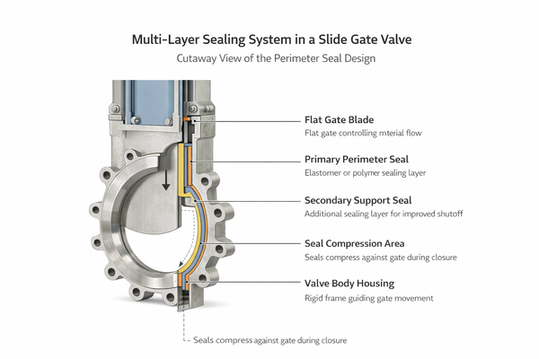
Key Sealing Mechanisms:
- Perimeter Seals: These are positioned around the edges of the gate and within the valve body.
- Flexible Seals (e.g., Urethane, EPDM, Silicone, PTFE, Felt): These are common, chosen for their elasticity and chemical resistance. They compress against the gate to create a tight seal when the valve is closed. The material choice depends on temperature, abrasion, and chemical compatibility.
- Jam-Proof Seals: Designed to prevent material from migrating into the seal area or jamming the gate. These often involve integral deflectors or hardened material contacting the gate.
- Internal Deflectors / Scrapers: Positioned at the inlet, these stationary components help redirect material away from the sealing surfaces and scraper blades clean the gate surface as it moves, preventing material buildup and ensuring a clean seal. This contributes to a *self-cleaning* aspect, reducing maintenance.
- Live Load Packing (for stem): For valves with external stems, a packing gland (often featuring braided PTFE or graphite) ensures a seal around the stem to prevent dust leakage to the atmosphere. Live loading mechanisms (e.g., spring washers) maintain constant compression on the packing, extending its life and sealing integrity.
- Inflatable Seals: For applications demanding absolute, bubble-tight shut-off (e.g., highly toxic or high-value materials), an inflatable seal around the gate can be pressurized with air once the valve is closed, expanding to create an impenetrable barrier.
- Parallel Slide Design: In a parallel slide gate valve, the gate slides between two parallel plates. Some advanced designs feature a mechanism that presses the gate against the downstream seat *after* it’s closed, providing an extremely tight shut-off, especially useful for very fine powders.
Operational Considerations for Longevity
Beyond the components themselves, how a slide gate valve is operated also impacts its lifespan and performance:
- Maintaining Cleanliness: Regular inspection of the sealing areas and gate ensures no material buildup compromises the seal.
- Material Characteristics: A particularly cohesive or sticky dry bulk material might require a specialized valve design to prevent bridging or jamming.
- Proper Actuator Sizing: An undersized actuator will struggle to move the gate, leading to premature failure. An oversized one can contribute to wear.
Conclusion: The Precision Behind Seamless Flow
The efficiency of dry bulk material handling machinery is often dictated by the performance of its valves. A well-designed slide gate valve, with its robust linear motion valve for bulk solids mechanism, carefully selected actuation system, and meticulously engineered slide gate valve sealing system design, is paramount for preventing costly downtime and ensuring process integrity.
From simple manual slide gate valves to sophisticated pneumatic single piston slide gate valves with advanced sealing (including aspects that support *self-cleaning* for the gate’s path), each component plays a vital role. BCST Valve commits to providing not just valves, but reliable solutions built on a deep understanding of these intricate systems.
Seeking expert advice for your dry bulk handling system?


 English
 Arabic
 Russian
 French
 Spanish