
Tank Protection & Vapor Control
Conservation Vent Manufacturer
BCST Valve manufactures conservation vents for controlling pressure and vacuum in atmospheric and low-pressure storage tanks. The valve remains closed during normal operating conditions and opens only when the specified pressure or vacuum setting is reached.
This controlled breathing action helps protect the tank structure while reducing unnecessary vapor loss, atmospheric intake and product contamination.
- Pressure-only, vacuum-only and combination designs
- Weight-loaded and spring-loaded configurations
- End-of-line and pipe-away arrangements
- Flame-arresting options for suitable applications
- Materials selected for the stored product and environment
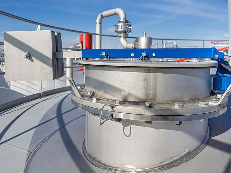
Tank Protection
Helps control excessive pressure and vacuum inside the storage tank.
Vapor Conservation
Limits unnecessary vapor release during normal tank operation.
Controlled Breathing
Opens at specified pressure or vacuum conditions and then reseats.
Factory Verification
Set-point and sealing checks within the agreed inspection scope.
Product Collection
Conservation Vent Types
Select the valve function, loading method and installation arrangement that match the tank protection requirements.
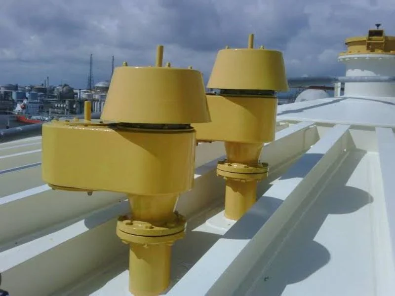
Pressure Vacuum Conservation Vent
Provides pressure relief and vacuum intake through separate pallets in one compact valve body.
- Combined pressure and vacuum protection
- Normal tank breathing service
- Multiple setting options
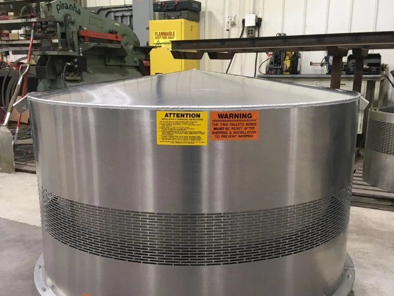
Flame-Arresting Conservation Vent
Combines pressure and vacuum breathing functions with an integrated flame-arresting element.
- Controlled tank breathing
- Integrated flame-arresting element
- Application review required
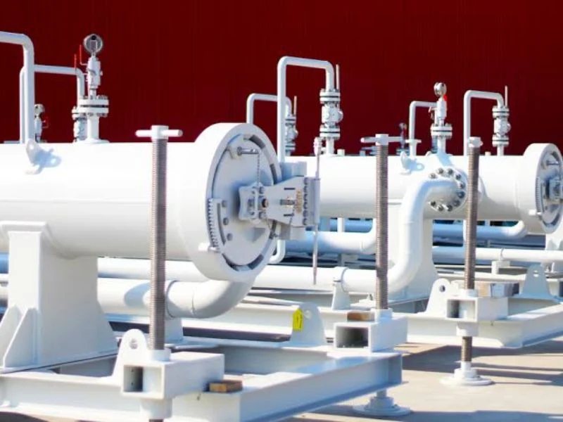
All-Weather Conservation Vent
An outdoor tank vent configuration designed for reliable operation under changing weather conditions.
- Weather-protected construction
- Compact valve arrangement
- Catalog sizes from DN50 to DN250
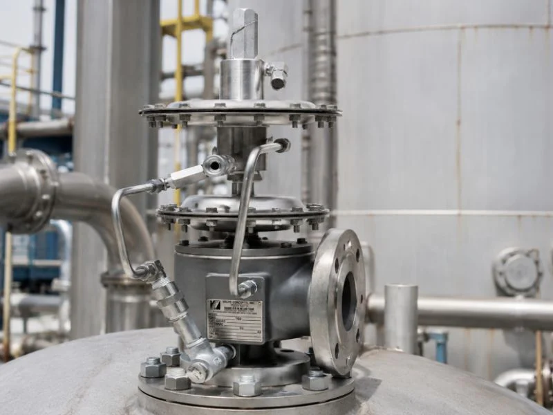
Pressure-Only Conservation Vent
Releases tank vapor when internal pressure reaches the selected opening setting.
- Single-exhalation function
- Direct or connected outlet
- Separate vacuum protection required
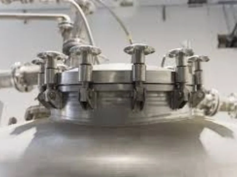
Vacuum-Only Conservation Vent
Admits air or inert gas when vacuum inside the tank reaches the specified condition.
- Single-suction function
- Direct or connected inlet
- Separate pressure protection required
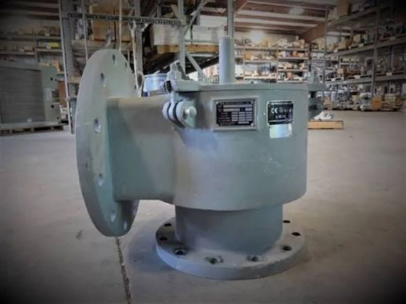
Pipe-Away Conservation Vent
Routes discharged vapor through connected piping to a recovery, flare or treatment system.
- Single or dual pipe connections
- Closed vapor handling systems
- Backpressure review required
Product Comparison
Select the Appropriate Conservation Vent
The correct configuration depends on the required function, vent piping and tank operating conditions.
| Vent Type | تخفيف الضغط | Vacuum Relief | Vapor Connection | Typical Application |
|---|---|---|---|---|
| Pressure Vacuum Vent | Yes | Yes | Direct discharge | Normal breathing of atmospheric tanks |
| Pressure-Only Vent | Yes | No | Direct or connected | Tanks with separate vacuum protection |
| Vacuum-Only Vent | No | Yes | Direct or connected | Air or inert-gas admission |
| Pipe-Away Vent | Model dependent | Model dependent | Closed piping | Vapor recovery and treatment systems |
| Flame-Arresting Vent | Model dependent | Model dependent | Direct or connected | Suitable flammable vapor applications |
| All-Weather Vent | Yes | Yes | Direct discharge | Outdoor storage tanks |
Operating Principle
How a Conservation Vent Works
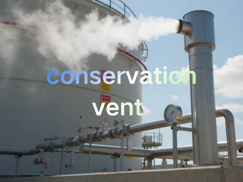
A conservation vent normally remains closed to retain tank vapor. It opens only when internal pressure or vacuum reaches the selected setting.
- Tank filling or thermal expansion increases internal pressure.
- The pressure pallet lifts at the specified opening condition.
- Vapor leaves the tank through the available flow path.
- Product withdrawal or cooling creates vacuum inside the tank.
- The vacuum pallet opens to admit air or inert gas.
- The pallets reseat when tank conditions return toward normal.
Set Pressure
Must remain safely within the allowable pressure limits of the tank.
Required Capacity
Must cover filling, withdrawal and thermal breathing requirements.
Stored Medium
Guides body, trim, seal and corrosion-resistance selections.
Piping Resistance
Must be considered when the vent connects to a vapor line.
Technical Data
Typical Pressure and Vacuum Settings
The following catalog values apply to selected configurations. Final settings must be confirmed against the tank design pressure, required capacity and project specification.
| Catalog Level | Pressure Setting | Vacuum Setting | Selection Guidance |
|---|---|---|---|
| أ | +355 Pa | -295 Pa | Low-pressure tank breathing |
| ب | +980 Pa | -295 Pa | Common catalog configuration |
| ج | +1765 Pa | -392 Pa | Higher positive-pressure setting |
| Custom | Specified by purchaser | Specified by purchaser | Subject to engineering review |
Available Sizes
Conservation Vent Size and Capacity Reference
Use the catalog information for preliminary comparison. Final valve sizing must be based on the required flow at the specified pressure and vacuum conditions.
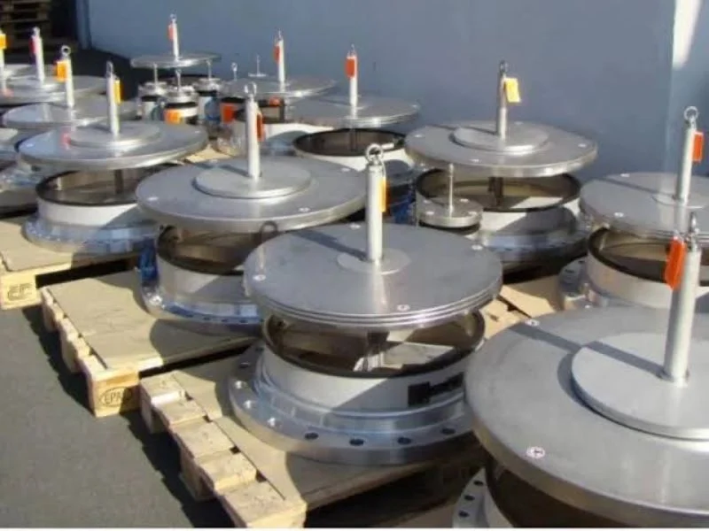
Catalog Size Range
- All-weather vent series: DN50 to DN250
- Flame-arresting vent series: DN50 to DN300
- Combination vent series: selected models up to DN400
- Pressure-only series: selected models up to DN500
- Alternative flange standards available upon review
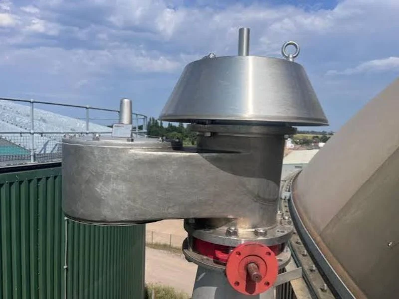
Important Sizing Notes
- Do not select a vent only by matching the tank nozzle size.
- Check pressure and vacuum capacity independently.
- Include thermal breathing in the capacity calculation.
- Consider pressure loss through flame-arresting elements.
- Include piping resistance and outlet backpressure.
Selected Catalog Airflow Capacity
| Nominal Size | Level A Pressure +355 Pa |
Level A Vacuum -295 Pa |
Level B Pressure +980 Pa |
Level C Pressure +1765 Pa |
|---|---|---|---|---|
| DN50 | 25 m³/h | 20 m³/h | 30 m³/h | 40 m³/h |
| DN80 | 60 m³/h | 50 m³/h | 70 m³/h | 95 m³/h |
| DN100 | 90 m³/h | 75 m³/h | 100 m³/h | 140 m³/h |
| DN150 | 190 m³/h | 160 m³/h | 200 m³/h | 280 m³/h |
| DN200 | 340 m³/h | 280 m³/h | 380 m³/h | 500 m³/h |
| DN250 | 500 m³/h | 450 m³/h | 600 m³/h | 800 m³/h |
Capacity values are catalog references for selected configurations. Confirm the model, test conditions and required operating point before ordering.
المواد
Material Options for Different Media
Material selection should consider the stored liquid, vapor composition, operating temperature, corrosion risk and site maintenance procedures.
| المكوّن | Typical Material Options |
|---|---|
| جسم الصمام | Aluminum alloy, carbon steel, SS304, SS304L, SS316 or SS316L |
| Valve Disc | Stainless steel or body-compatible alloy |
| Guide Rod | الفولاذ المقاوم للصدأ |
| Flame-Arresting Element | Stainless steel, model dependent |
| Valve Seal | PTFE or application-specific material |
Selection Checklist
Information Required for Technical Selection
Complete operating data allows the manufacturer to review venting capacity, settings, materials and installation compatibility.
Tank Data
- Tank type and storage volume
- Maximum allowable pressure
- Maximum allowable vacuum
- Vent nozzle size and rating
- Normal and emergency venting arrangement
Process Data
- Stored liquid and vapor composition
- Maximum filling rate
- Maximum withdrawal rate
- درجة حرارة التشغيل
- Minimum ambient temperature
Project Requirements
- Pressure and vacuum settings
- Body, trim and seal materials
- Flange standard and facing
- Direct or pipe-away installation
- Inspection and document requirements
التطبيقات
Conservation Vent Applications
Conservation vents are used on atmospheric and low-pressure storage tanks that require controlled breathing and reduced vapor loss.

النفط والغاز
Tank breathing and vapor control for petroleum products and hydrocarbons.

Tank Farms
Pressure and vacuum protection for bulk storage and distribution terminals.

المعالجة الكيميائية
Material-compatible venting for chemicals, solvents and process liquids.

مصافي التكرير
Normal breathing and vapor-management solutions for refinery storage tanks.
Manufacturer Quality Control
Inspection Before Delivery
The inspection scope is confirmed during order review. Available checks depend on the selected conservation vent model and agreed documentation requirements.
- Review the approved datasheet and product drawing.
- Verify body, internal and sealing materials.
- Inspect dimensions, connections and product markings.
- Check pressure and vacuum opening settings.
- Inspect seat sealing and free pallet movement.
- Review documentation and protective packing.

Installation & Maintenance
Maintain Reliable Venting Performance
Correct installation and routine inspection help preserve the intended set points, sealing performance and airflow capacity.
Installation Guidelines
- Install the conservation vent in the specified orientation.
- Keep the tank nozzle and vent passage clean.
- Avoid transferring piping loads to the valve body.
- Check that the pallets move freely before commissioning.
- Consider backpressure in pipe-away applications.
- Provide safe access for inspection and maintenance.
Maintenance Guidelines
- Inspect screens and flow passages for blockage.
- Clean deposits from pallets and seating surfaces.
- Examine seals for wear or chemical damage.
- Inspect flame-arresting elements where fitted.
- Do not alter pallet weights without authorization.
- Verify operation before returning the valve to service.
 English
 Arabic
 Russian
 French
 Spanish