
Your control valve responds too slowly in an emergency. This lag risks safety and can cause catastrophic process failures. An SOV (Solenoid Valve) provides the instant shutdown you need.
An SOV, or Solenoid Operated Valve, is a fast-acting switch that controls the air supply to your pneumatic actuator. It uses an electromagnet to instantly open or close an air path, forcing the main control valve to its fail-safe position for emergency shutdown or rapid control.
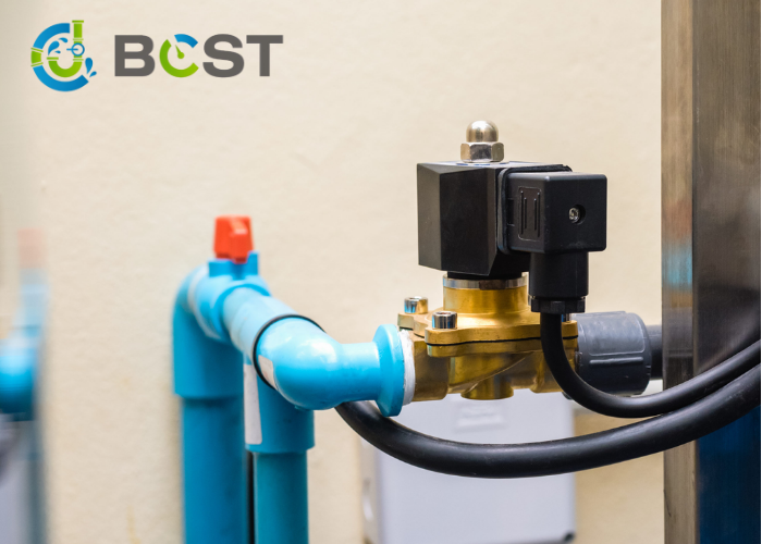
In my years visiting chemical plants and refineries, I’ve seen how a single component can be the difference between a normal day and a complete disaster. I once discussed this with Hassan, a Chief Engineer for a petrochemical project. He pointed to a control valve and said, “Emily, the positioner is the brains for fine-tuning, but the SOV is the reflex. It doesn’t think, it just acts. When everything goes wrong, it’s the SOV that saves the plant.” This simple statement perfectly captures the vital role of the solenoid valve. It’s not just an accessory; it’s a fundamental safety device. Let’s break down exactly how this small but mighty component protects your most critical processes.
What Is an SOV in a Control Valve?
It seems impossible that a small electrical device can slam shut a huge pipeline valve. You’re wondering how this simple magic trick works. The secret lies in a basic electrical principle.
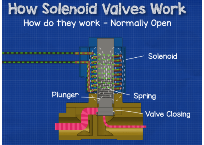
A solenoid valve uses electromagnetism to pilot a much larger force: compressed air. When electricity flows through its coil, a magnetic field moves a small plunger, which reroutes the air supply to or from the main valve’s actuator, causing it to move instantly.
The Core Principle and Its Role
To truly understand the importance of an SOV, you need to grasp how simply and reliably it works. It doesn’t perform complex calculations. It is a binary, on-off device that excels at one thing: moving fast. This speed is what makes it indispensable in any automated industrial process.
The Electromagnetic Switch
At its heart, the solenoid valve is an electromechanical switch for air.
- De-Energized State: With no power, a spring holds a metallic plunger (or core) in a default position. This either blocks or allows air to pass through the valve body, depending on its design.
- Energized State: When you send an electrical signal to the coil, it creates a powerful magnetic field. This magnetic force overcomes the spring pressure and moves the plunger to its second position.
- Action: This movement of the plunger instantly redirects the flow of instrument air. It either pressurizes the actuator to open/close the valve or vents the air, allowing the actuator’s springs to force the valve into its fail-safe position.
Types of Solenoid Valves
The default state of the SOV is a critical design choice. It determines what happens when power is lost.
| نوع الصمام | No Power (De-Energized) | Power On (Energized) | الاستخدام الشائع |
|---|---|---|---|
| Normally Closed (NC) | The valve is closed, blocking air flow. | The valve opens, allowing air to pass. | Venting air to trigger a fail-safe action. |
| Normally Open (NO) | The valve is open, allowing air to pass. | The valve closes, blocking air flow. | Supplying air to hold a valve in position. |
| 3-Way / 4-Way | These have extra ports to control dual-acting actuators or more complex logic, routing air between different paths. | Provides inlet, outlet, and exhaust functions. | Control of actuators without spring return. |
The SOV’s primary role in a control valve assembly is to act as an override. It bypasses the slower, modulating signal from a positioner to execute an immediate and decisive action, usually for an Emergency Shutdown (ESD).
Is Your Single صمام الملف اللولبي a Ticking Time Bomb for Your Process?
Your critical process is protected by a single solenoid valve. But what happens if that one valve fails? A stuck plunger or burnt-out coil means your safety function is gone.
A single SOV represents a single point of failure. If it malfunctions, your entire shutdown system is compromised. For critical applications, a single point of failure introduces an unacceptable level of risk that could lead to process disruption or a safety incident.
 Embracing Redundancy with Dual SOVs
In non-critical applications, a single SOV is often sufficient and cost-effective. However, when you’re dealing with flammable materials, high pressures, or processes where failure is not an option, you need another layer of protection. This is where a dual SOV configuration becomes essential. Hassan would never sign off on a critical safety system design without it. “One is none, and two is one,” he’d say, emphasizing that you must have a backup.
Limitations of a Single SOV Configuration
A single SOV is simple and cheap. It is installed in the air line between the positioner and the actuator. When energized, air passes through; when de-energized, the air is vented. But think about what can go wrong:
- Coil Burnout: The electrical coil fails, preventing it from switching states.
- Plunger Sticking: Debris or corrosion causes the internal plunger to get stuck.
- Electrical Fault: A blown fuse or broken wire means the signal never reaches the SOV.
In any of these cases, your emergency shutdown capability is lost, and you won’t know it until you need it most.
How a Dual SOV Provides Higher Reliability
A dual SOV system uses two solenoid valves in a specific logic arrangement (often 1-out-of-2 or 2-out-of-2) to ensure the fail-safe action can occur even if one component fails.
For example, in a common redundant setup for venting:
- Normal Operation: Both SOVs are energized, blocking the exhaust path and allowing air to pass from the positioner to the actuator.
- Shutdown Triggered: The signal to both SOVs is cut.
- Redundant Action: If SOV-1 works, it opens the exhaust path and the valve fails safe. If SOV-1 is stuck but SOV-2 works, ذلك opens an alternate exhaust path, and the valve still fails safe. The shutdown only fails if both SOVs get stuck in the closed position simultaneously, which is statistically very unlikely.
| Failure Scenario | Single SOV Result | Dual SOV (1oo2 Logic) Result |
|---|---|---|
| SOV coil fails (stuck energized) | FAILURE TO SHUT DOWN | Success. The second SOV de-energizes and vents air. |
| Debris clogs one SOV’s exhaust | FAILURE TO SHUT DOWN | Success. The second SOV provides a clear exhaust path. |
| Nuisance trip (false signal) | Triggers shutdown | Can be designed to require signal loss from both channels. |
This redundancy is why dual SOVs are a standard requirement for Safety Instrumented Systems (SIS) and are essential for achieving a higher Safety Integrity Level (SIL).
Why Is Placing the SOV Before the Positioner a Non-Negotiable Safety Rule?
You might think the signal path should be neat: DCS to positioner to SOV. This seems logical, but it’s dangerously wrong. It puts a slow, thinking device in front of a fast, reactive one.
ال SOV must be installed in the air line قبل the positioner to ensure the fastest possible response. This allows the SOV to directly cut off air and vent the actuator without waiting for the positioner’s slower internal process.

Prioritizing Speed and Reliability
In control engineering, the sequence of components is everything. Placing the SOV correctly is one of the most fundamental rules for building a reliable shutdown system. This isn’t just a suggestion; in many industries, it’s a requirement dictated by standards like SHT3005. The reason boils down to one word: speed.
The Positioner: Precise but Slow
A smart positioner is a microprocessor-based device. It receives a control signal (e.g., 4-20mA) from the DCS, compares it to the valve’s actual position, and then makes fine adjustments to the air pressure in the actuator. This process involves diagnostics, calculations, and measured movements. It is designed for accuracy, not raw speed. In an emergency, this processing time is a dangerous delay.
The SOV: The Physical Override
By placing the SOV on the main instrument air supply line that feeds the positioner, you create a physical “kill switch.” When the Safety Interlock System (SIS) detects an emergency, it doesn’t send a command to the DCS to “please close the valve.” It sends a direct signal to the SOV.
- Direct Action: The SOV immediately cuts off the air supply ل the positioner.
- Immediate Venting: The SOV simultaneously opens a large exhaust port, rapidly venting all the air from the actuator.
- Bypassing the Delay: The positioner is completely taken out of the loop. It doesn’t matter what the positioner was thinking or doing. The air is gone, and the actuator’s spring takes over, forcing the valve to its fail-safe position in seconds.
This configuration protects against multiple failure modes:
- DCS/Positioner Failure: If the positioner freezes or the control signal is lost, the SOV can still function independently based on the SIS signal.
- Maximum Reliability: The shutdown path is the simplest and most direct possible: SIS → SOV → Actuator. Fewer components mean fewer things can go wrong. Real-world engineering always favors this robust simplicity for safety.
How Can You Spot a Failing Solenoid Valve Before It Fails You?
Your SOV sits on a valve and does nothing for months. How do you know it will work when needed? You can’t just trust it; you need to know the signs of trouble.
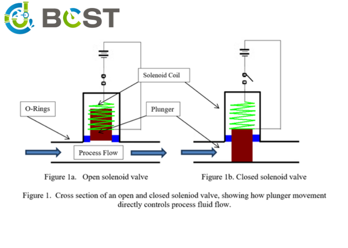
You can evaluate an SOV’s health with simple, quick checks. Monitor its operating temperature, test its electrical coil resistance, and perform a mechanical check to ensure it’s not stuck or blocked.
A Practical Guide to SOV Health Checks
An SOV may seem like a “fit and forget” component, but proactive evaluation is crucial for reliability. You don’t need to disassemble it every time. A few non-intrusive tests can give you a clear picture of its health. Here are the key checks you should integrate into your maintenance rounds.
1. Temperature Monitoring
An energized solenoid coil will always be warm to the touch. The key is to look for abnormal temperatures.
- How to Check: Use a non-contact infrared pyrometer.
- What to Look For:
- Too Hot: An excessively hot coil can indicate high voltage, an internal short circuit, or that the plunger is not fully seated, causing the coil to draw extra current.
- Too Cold: A coil that is cold while energized means no current is flowing. This points to a failed coil, a blown fuse, or a wiring problem.
- Comparison: In a dual SOV system, the two coils should have a temperature difference of less than 5°C. A significant variance indicates a problem with one of them.
2. Electrical Checks
The coil is the most common failure point. A simple resistance check can confirm its integrity.
- How to Check: De-energize the valve and use a multimeter to measure the resistance (in Ohms) across the coil’s terminals.
- What to Look For:
- Infinite Resistance (Open Loop): The coil winding is broken. The coil is dead.
- Zero Resistance (Short Circuit): The windings have shorted out. This will likely blow the fuse.
- Correct Resistance: Compare the reading to the manufacturer’s specification or a known good coil.
3. Mechanical and Functional Inspection
You must also verify that the valve can move freely.
- Exhaust Port Check: The exhaust port is often left open to the atmosphere. It can get clogged by insect nests, ice, or corrosion. A blocked exhaust means the actuator cannot vent, and the valve will not fail-safe. Ensure it is clear and protected with a bug screen.
- Manual Operator: Some SOVs have a manual override lever or button. During a planned shutdown, you can use this to manually cycle the valve and confirm it is not mechanically stuck.
- Partial Stroke Test: In advanced SIS systems, a “partial stroke test” can be performed. This commands a very brief (e.g., 1-second) de-energization of the SOV to see if the actuator begins to move, confirming the entire shutdown mechanism is free and ready to act without fully disrupting the process.
| Check Type | Tool | What it Detects | Red Flag |
|---|---|---|---|
| درجة حرارة | Pyrometer | Over-current, under-current, internal shorts. | Excessively hot, cold, or >5°C difference. |
| Electrical | Multimeter | Broken coil windings, short circuits. | Infinite or near-zero resistance. |
| Mechanical | Visual/Manual | Stuck plunger, blocked exhaust path. | Blockage in exhaust, failure to manually operate. |
الأسئلة الشائعة
Q1: What voltage should I choose for SOV?
A: Depends on your control system. DC 24V is most common in modern DCS/PLC systems…
Q2: How often should SOV be maintained?
A: BCST recommends quarterly inspection for critical applications…
Q3: Can SOV work in extreme temperatures?
A: Yes, BCST offers special models rated for -40°C to +150°C…
Q4: What’s the difference between 2-way and 3-way SOV?
A: 2-way controls on/off; 3-way switches between two air sources…
Q5: How to select fail-safe mode?
A: Fail-close (FC) for shut-off valves; Fail-open (FO) for bypass valves…
خاتمة
ال SOV is the unsung hero of control valve safety. It delivers the speed and reliability that your process depends on in an emergency. For critical systems, always choose a redundant dual SOV configuration.


 English
 Arabic
 Russian
 French
 Spanish