
A Technical Guide to Calibration
In industrial processes where precision is paramount, a пневматический регулирующий клапан is a critical component influencing flow, pressure, and temperature. Yet, even the most advanced valve is only as effective as its installation, maintenance, and, crucially, its calibration. A mere 1% error in valve calibration can translate into significant efficiency losses, product quality inconsistencies, or even safety hazards running into thousands of dollars in a complex system.
This guide provides a field-ready, technical roadmap for professionals to ensure their pneumatic control valves operate at peak performance. We’ll cover essential pneumatic control valve installation practices, how to safely use pneumatic valve manual override features, and a detailed, step-by-step procedure for how to calibrate pneumatic control valve settings—including crucial zero and span adjustments and linearity checks. Before installing, ensure you have selected the correct Pneumatic Control Valve Type for your specific application requirements.

Pneumatic Control Valve Installation Best Practices
The foundation of a reliable пневматический регулирующий клапан system begins with meticulous installation, particularly focusing on the quality of its lifeblood: compressed air.
Instrument Air Requirements: The Importance of Clean, Dry Air
The performance and longevity of a пневматический регулирующий клапан are critically dependent on the quality of its instrument air supply. Poor air quality is the leading cause of premature failure for actuators and positioners. To prevent critical issues like positioner clogging, seal degradation, and internal corrosion, instrument air must be:
Instrument Air Quality Checklist:
- Clean: Free from solid particulate matter (e.g., dust, rust) larger than 5 microns. These can clog small orifices in the позиционер or cause abrasive wear in the привод.
- Dry: Moisture-free with a dew point at least 10°C (18°F) below the lowest ambient temperature. Moisture leads to condensation, internal corrosion, and potential freezing in cold environments, which can entirely disable a valve.
- Oil-Free: Contains no more than 1 ppm (parts per million) by weight of oil vapor. Oil can degrade internal elastomeric seals (O-rings, diaphragms), cause components to stick (stiction), and attract dust, leading to sluggish or erratic valve operation.
Managing Air Quality: The Role of Upstream Air Filter Regulators
To ensure consistent and high-quality instrument air, an air filter regulator (AFR) should always be installed upstream of the positioner. This device combines a filter to remove particulates and moisture, and a pressure regulator to maintain a stable supply pressure to the pneumatic instruments, typically around 20-30 psi (1.4-2.1 bar) for the actuator and positioner supply. Regular inspection and replacement of AFR filter elements are crucial for maintaining instrument air quality standards.
How to Control Pneumatic Valve Shut Off & On: Manual vs. Automated Overrides
While pneumatic valves are designed for continuous, automated control, understanding their manual override capabilities is crucial for safe operation, troubleshooting, and maintenance.
Automated Control: The Standard Loop (Controller + Positioner)
Under normal operation, the пневматический регулирующий клапан is managed by its automated control loop. An external controller (e.g., DCS, PLC) sends an electrical signal (e.g., 4-20mA) to the позиционер. The positioner, incorporating an I/P transducer, converts this electrical signal into a proportional signal pressure (typically 3-15 psi or 0.2-1.0 bar) and applies it to the привод. The actuator then moves the valve stem to the precise commanded position, regulating fluid flow automatically.
Manual Overrides: Using Handwheels and Levers for Maintenance and Emergency Shutdowns
Many pneumatic actuators are equipped with a manual override feature, usually a handwheel or lever. This allows technicians to bypass the pneumatic control system and physically move the valve stem to a desired position without the need for instrument air or an electrical signal. This capability is invaluable during:
- Startup/Shutdown: Safely positioning valves during initial plant startup or sequenced shutdowns.
- Обслуживание: Placing the valve in a safe, isolated position (e.g., fully closed) before initiating work on the valve or downstream equipment.
- Emergency Scenarios: Manually moving a valve to its fail-safe position if automated systems are compromised.
Safety During Maintenance: When to Engage Local Overrides to Protect Technicians
When performing any work on or near a пневматический регулирующий клапан, engaging the local manual override is a critical component of a safe work permit procedure. This ensures the valve remains in a known, safe position, preventing unexpected movements. Always remember to:
- Verify that the instrument air supply to the actuator is completely isolated and vented.
- Lock out and tag out any electrical power to the positioner or электромагнитный клапан.
- Use the manual override to positively confirm the valve is in its desired safe state (e.g., closed for isolation) before proceeding with work.
Maintenance: How to Calibrate and Adjust a Pneumatic Control Valve
Accurate calibration of pneumatic control valves is fundamental for maintaining process stability. Over time, wear, temperature changes, or mechanical adjustments can lead to “drift,” causing the valve to respond inaccurately to its control signal. This can result in system hunting (oscillation), sluggish response times, or consistent offset from the desired setpoint. According to reports by mecatork, Pneumatic ball valves commonly fail due to air supply issues, actuator problems, and sealing wear, with failure rates varying by model and testing (e.g., 76-362 FIT for dangerous failures in some actuators). Weekly inspections in chemical plants prevent 78% of catastrophic failures, boosting MTBF from 57% to 89% with predictive maintenance.
Why Calibration Matters: Avoiding Oscillation and Sluggish Response Times
Правильно zero and span adjustments ensure that the valve’s full physical stroke aligns perfectly with the full range of its control signal. When calibration is off, a 50% signal might only result in 40% valve opening, or the valve might not fully open or close. This non-linearity leads to poor control performance, increased energy consumption, and product quality issues. Regular calibration, usually performed annually or biannually, mitigates these costly problems.
Step-by-Step Guide to Zero and Span Adjustments for Precision
Follow these steps to accurately calibrate a пневматический регулирующий клапан, ensuring its full travel aligns with the 3-15 psi (0.2-1.0 bar) standard signal pressure:
- Connect Calibration Equipment:
Isolate the valve from process flow and release internal pressure. Connect a precision pressure source (calibrator) to the positioner’s input and a calibrated pressure gauge to its output. Attach a precise stem measurement tool (e.g., ruler, dial indicator) to monitor the actual valve travel.
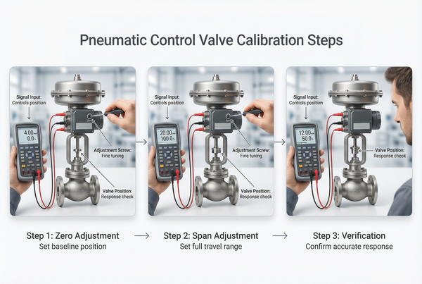
Figure 2: Typical Setup for Pneumatic Control Valve Calibration - Zero Adjustment: Setting the Minimum Benchmark:
Apply the minimum input signal pressure (e.g., 3 psi) from your calibrator to the positioner. Adjust the positioner’s “zero” screw (or pot for digital positioners) until the valve stem reaches its exact minimum position (e.g., 0% open for a Fail-Closed valve, or 100% open for a Fail-Open valve). Ensure there’s no movement below this point.
- Span Adjustment: Setting the Maximum Benchmark:
Apply the maximum input signal pressure (e.g., 15 psi). Adjust the positioner’s “span” screw until the valve stem reaches its exact maximum position (e.g., 100% open for a Fail-Closed valve, or 0% open for a Fail-Open valve). This sets the full range of the valve’s travel.
- Linearity Check: Verifying Intermediate Flow Points:
After setting zero and span, cycle the valve through several intermediate input signal pressures (e.g., 6 psi, 9 psi, 12 psi, corresponding to 25%, 50%, 75% stroke). Record the actual stem position at each point. If the valve’s response is not linear (e.g., 9 psi should yield 50% stroke), fine-tune the zero and span adjustments by repeating steps 2 and 3 until satisfactory linearity is achieved. A slight tolerance is usually acceptable (e.g., ±1-2%).
- Fail-Safe Confirmation: Testing Loss-of-Air Scenarios:
Crucially, test the valve’s fail-safe position verification. Slowly depressurize the instrument air supply to the actuator. The valve should smoothly and reliably move to its designed fail-open (FO) или fail-closed (FC) position. This confirms that in an emergency or power/air loss, the valve will default to its safest state, which is a critical safety parameter for pneumatic control valve maintenance.
Calibration Data Reference (Fail-Closed Valve Example)
Below is an example of a calibration table for a Fail-Closed (FC) pneumatic control valve. This table helps track performance and ensures precise linearity check for control valves across their full operating range. Deviations highlight areas for adjustment.
Measured Stem Position vs. Input Signal Table
| Input Signal (psi) | Desired Valve Opening (%) | Measured Stem Position (%) | Deviation (%) | Correction Needed |
|---|---|---|---|---|
| 3 psi | 0% (Closed) | 0% | 0% | Verify Zero |
| 6 psi | 25% | 26% | +1% | Minor Linear Adjust |
| 9 psi | 50% | 49% | -1% | Minor Linear Adjust |
| 12 psi | 75% | 74% | -1% | Minor Linear Adjust |
| 15 psi | 100% (Open) | 99% | -1% | Adjust Span |
Troubleshooting Common Calibration and Installation Errors
Even with meticulous care, issues can arise. Knowing how to troubleshoot common problems is vital for efficient pneumatic control valve maintenance.
Handling “Hunting” and Overshoot: Tuning the Positioner Sensitivity
If your valve is “hunting” (oscillating around the setpoint) or overshooting its commanded position, it’s often a sign that the позиционер‘s sensitivity (gain) is too high, or there’s excessive stiction in the valve stem. Adjust the positioner’s tuning parameters (often labeled gain, derivative, integral) cautiously. For severe stiction, mechanical inspection and lubrication of the stem packing may be required. This is a common aspect of how to adjust pneumatic flow control valve behavior.
Identifying Seal Degradation: How Oil-Contaminated Air Ruins O-rings
Erratic valve movement, visible leaks at the actuator, or failure to hold position can indicate degrading seals. A surprisingly common culprit is oil-contaminated instrument air. Oil breaks down common elastomer (rubber) seals and O-rings, leading to leaks, increased friction (stiction), and eventual failure. Regular checks of your instrument air quality standards and proactive replacement of air filter regulators can prevent this. For a more detailed look into pneumatic control valve operation, refer to our Pneumatic Control Valve Guide.
Frequently Asked Questions (FAQ)
Q: How do I identify a “Fail-Open” vs. “Fail-Closed” valve?
A Fail-Open (FO) valve will spring fully open upon loss of instrument air pressure, while a Fail-Closed (FC) valve will spring fully closed. You can often identify this by observing the actuator’s spring casing (springs typically push or pull against air pressure) or by checking the valve’s technical documentation and nameplate. Loss of air and observing valve position is the definitive, albeit careful, test.
Q: What is the standard signal pressure for industrial pneumatic valves?
The widely accepted industry standard for the control signal pressure range that positions the valve is 3–15 psi (pounds per square inch) or 0.2–1.0 bar. This range is used by the позиционер to convert an electrical signal (commonly 4-20mA DC) into a proportional pneumatic output to drive the actuator.
Q: Why does my valve drift from its setpoint?
Valve drift can be caused by several factors: miscalibration (zero and span adjustments not accurate), excessive friction or stiction in the valve packing, internal leakage within the positioner or привод, fluctuating instrument air supply pressure, or changes in process conditions (pressure drops, fluid forces) that the positioner struggles to compensate for. A systematic troubleshooting approach, starting with calibration of pneumatic control valves, is usually required.
Q: How often should I check instrument air filters?
The frequency of checking instrument air filters depends heavily on the quality of your compressed air system and the environmental conditions. However, a good practice is to visually inspect the filter elements and drain the bowls monthly. Replace filter elements at least quarterly, or immediately if discoloration, excessive moisture accumulation, or pressure drop across the filter is observed, to maintain optimal instrument air quality standards.
Заключение
For organizations relying on precise process control, pneumatic control valve installation and maintenance are not expenses, but critical investments in operational integrity. From ensuring impeccable instrument air quality during setup to executing meticulous zero and span adjustments during calibration, every technical detail contributes to the valve’s longevity, accuracy, and overall system efficiency.
By treating these valves with the diagnostic and preventative care they demand, industrial facilities can significantly reduce costly downtime, improve product consistency, and ensure the highest safety standards. Precision installation and regular, expert calibration are the undisputed keys to achieving optimal valve performance and maximizing the lifespan of your critical assets.
Need high-performance positioners or expert technical support for your valve assembly?


 English
 Arabic
 Russian
 French
 Spanish