
A Technical Guide to Flow Patterns
Key Distinctions: L-Port vs. T-Port 3-Way Ball Valves
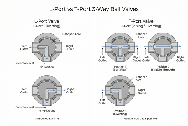
- L-Port (Diverter): Connects a common port to one of two side ports. Cannot mix or provide straight-through flow. Ideal for distinct fluid diversion.
- T-Port (Mixer/Bypass): More versatile, capable of connecting three ports simultaneously for blending applications, or providing straight-through flow.
- Rotation: L-Port typically 90-degree for two positions; T-Port can use 90-degree or 180-degree to access all possible multi-port flow paths.
- Selection Criticality: Mismatching the flow pattern to the application leads to system inefficiency or malfunction.
In the world of industrial fluid control, the 3-way ball valve offers remarkable versatility, but its potential can only be fully realized by understanding its internal mechanics. The most critical decision in selecting a 3-way ball valve often boils down to a single question: do you need an L-Port or a T-Port? This choice—the internal bore orientation—dictates how fluids will intersect, diverge, or blend within your piping system. For engineers, installers, and process owners, confusing these two configurations is a common oversight that can lead to frustrating operational issues, unexpected pressure drop, or even system downtime.
This technical guide aims to eliminate that confusion. We will provide a clear, mechanical breakdown of how fluid moves through each L-port vs T-port 3 way ball valve configuration. Our goal is to clarify the specific 3 way ball valve flow patterns each offers, demystify the nuances of handle rotation, and highlight their optimal industrial applications. Before diving into flow patterns, ensure you understand the basic components and selection criteria in our Comprehensive 3-Way Ball Valve Guide.
What is an L-Port 3-Way Ball Valve? (The Diverter)
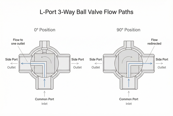
The L-Port 3-way ball valve, often referred to as a 3 way diverter valve, excels at directing incoming flow to one of two potential outlets. It acts like a switch, ensuring that the fluid takes one path OR another, but never simultaneously both.
Mechanical Configuration: The “L” Shaped Hole
The core of an L-Port valve is a spherical ball with an “L” shaped passage bored through it. This L-shaped hole is designed to connect a designated common port to either of the two side ports. When the valve is operated, the L-shaped bore rotates, moving the connection point between the two side ports while always keeping one port blocked. A typical L-port 3 way ball valve 90 degree turn will shift the flow from connecting the common port to one side port, to connecting the common port to the other side port.
Primary Use Case: Diverting Flow (Switching Between Tank A and Tank B)
The L-Port valve’s specialty is fluid diversion. Consider a scenario where you’re drawing fuel from one of two large storage tanks. An L-Port 3-way ball valve can be installed to allow the pump to draw from Tank A or switch to Tank B, ensuring the supply line always connects to only one source at a time. Other applications include switching between two different process lines or directing a single fluid stream to one of two destinations.
Limitations of the L-Port: No Mixing or Straight-Through Flow
While excellent for diverting, the L-Port has clear limitations. It cannot mix two incoming fluids into a single outlet because its design always blocks one of the side ports when the common port is connected to another. Similarly, it cannot provide a straight-through flow connecting the two side ports while completely isolating the common port, nor can it connect all three ports simultaneously. This is a critical distinction that often leads to errors in system design if its capabilities are misunderstood.
What is a T-Port 3-Way Ball Valve? (The Mixer/Bypass)
In contrast to the L-Port, the T-Port 3-way ball valve offers greater flexibility, capable of mixing, diverting, or providing a bypass function depending on its rotational position. It’s often referred to as a 3 way mixing valve or a bypass valve.
Mechanical Configuration: The “T” Shaped Bore
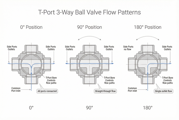
The T-Port valve features a ball with a “T” shaped hole. This configuration allows for the connection of three ports simultaneously in certain positions, or a straight-through connection between two ports while the third is open to the flow. The versatility of the T-port 3-way ball valve diagram demonstrates its ability to handle more complex multi-port flow paths.
Primary Use Case: Mixing and Blending (Combining Two Sources into One Outlet)
A common application for T-Port valves is blending applications. For instance, two different fuel additives might need to be combined into a single main fuel line. A T-Port valve can allow both additives to flow simultaneously into the main line, effectively mixing them. This is impossible with an L-Port valve.
The Bypass Function: Straight-Through Flow While Closing the Third Port
Another powerful feature of the T-Port is its ability to provide a straight-through flow between two opposing ports (e.g., ports 1 and 3) while blocking the third port (port 2). This makes it ideal for bypass lines in pump systems, where you might want to divert flow around a piece of equipment for maintenance, or maintain flow in a loop while temporarily isolating a section. The T-shape allows for this flexibility, where the L-Port would necessarily block one of the through-flow paths.
Ball valve studies show variable flow coefficients and pressure drops based on port design and opening angle, but no direct L vs. T stats exist; general tests indicate ball valves maintain low resistance across configurations.
L-Port vs. T-Port: Key Differences at a Glance
The differences between L-Port and T-Port valves can be summarized concisely to aid in quick selection.
| Характеристика | L-Port (Diverter) | T-Port (Mixer/Bypass) |
|---|---|---|
| Mixing Capability | No (always blocks one side port) | Yes (can connect all three ports) |
| Diverting Capability | Yes (common port to either side) | Yes (can divert analogous to L-Port) |
| Number of Active Flow Positions | Typically 2 (at 0° and 90°) | Typically 3 or 4 (depending on 90° vs 180° rotation) |
| Straight-Through Flow | No (without blocking the common port) | Yes (connecting two opposing ports) |
| Best Industry Application | Tank selection, alternating process lines | Blending, recirculation loops, bypass lines |
Flow Patterns and Handle Rotation
Understanding how the handle or actuator rotation translates to internal flow is fundamental for control and avoiding common installation mistakes regarding port orientation.
90-Degree vs. 180-Degree Operation
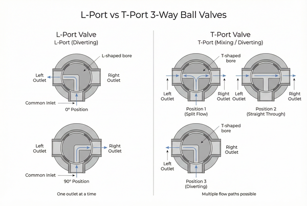
Most L-Port valves typically use a 90-degree rotation for two distinct flow positions. The handle moves a quarter turn to divert flow. For T-Port valves, operation can be more complex. A 90-degree turn can activate certain T-Port functions (e.g., switching from mixing to straight-through flow). However, some T-Port applications, particularly those requiring all possible flow states, might utilize a 180-degree rotation. It’s crucial that the actuator matches the valve’s rotational requirements.
Visualizing the Ball Position: The T-Port’s 180-Degree Sequence
Let’s consider a T-Port valve with a common port at the bottom (6 o’clock) and two side ports (9 and 3 o’clock). Imagine the handle is aligned with the pipe:
- 0° Position (Handle aligned with pipe): The T-shaped bore within the ball might connect the common port to both side ports (mixing) or allow straight-through flow between the side ports and block the common port. This depends on the specific manufacturer’s design.
- 90° Position (Handle perpendicular to pipe): A quarter turn will reorient the T-bore. This could activate a diversion, connecting the common port to one side port, or connect all three for mixing if the 0° position was straight-through.
- 180° Position (Handle aligned with pipe, opposite 0°): If the valve allows 180-degree rotation, this position will offer another, often distinct, flow pattern. For example, if 0° allowed mixing, 180° might allow straight-through flow. The key is that the “T” shape allows for multiple stable flow patterns within a relatively small amount of rotation.
Common
Installation Mistake: Incorrectly assuming the common port’s orientation or misunderstanding the handle’s indication for internal flow. Always refer to the manufacturer’s provided flow pattern diagrams for your specific valve model to prevent misdirection of flow. Stopping the handle mid-rotation (e.g., 45 degrees) for T-ports can also lead to turbulent flow, cavitation, and accelerated seat wear.
Industrial Applications in the Fuel Industry
Both L-Port and T-Port valves play vital roles in the fuel industry, each specialized for distinct operational needs.
Fuel Recirculation Loops: Why T-Ports are Used for Bypass Systems
T-Port valves are frequently deployed in fuel recirculation loops to maintain constant flow or pressure, typically around pumps and filters. They can act as a bypass, allowing a portion of the flow to return to the suction side of a pump, thereby controlling flow rate or preventing pump cavitation or deadheading. Their ability to provide a straight-through path while allowing diversion makes them perfect for these process-critical applications.
Multi-Tank Distribution: Why L-Ports Are Standard for Fuel Manifold Systems
In contrast, L-Port valves are the standard for fuel manifold systems involved in multi-tank distribution. When transferring fuel from various storage tanks to a common supply line, or vice-versa, L-Ports ensure that only one tank is connected at a time, preventing unintended mixing or contamination between different fuel types or batches. Their clear, diverting A-to-B capability is precisely what’s needed here.
Frequently Asked Questions (FAQ)
Q: Can I turn an L-port into a T-port by changing the handle?
No, absolutely not. The distinction between an L-Port and a T-Port valve lies in the actual drilling pattern of the spherical ball inside the valve body. This internal bore orientation is a fundamental part of the valve’s design and cannot be altered by simply changing the handle or actuator. Attempting to force a valve to perform a function it wasn’t designed for will likely lead to operational failure, internal damage, or dangerous leaks.
Q: Which port is usually the ‘Common Port’?
While it can vary by manufacturer and specific design, the common port is often the bottom port in a 3-way valve with a side-entry configuration, or the central port in a valve with an inline configuration. However, relying on this assumption can be risky. Always consult the manufacturer’s documentation, flow diagrams, or the valve’s body markings (if available) to precisely identify the common port and correctly orient the valve during installation.
Q: What happens if I stop the handle at 45 degrees?
Stopping a 3-way ball valve handle at an intermediate position (e.g., 45 degrees between fully open positions) is generally not recommended and can be detrimental. It creates a partially throttled flow, which can lead to increased velocity, turbulence, and significant pressure drop. This turbulent flow can cause cavitation, which is highly damaging to the valve’s internal components, particularly the seats. It can also lead to erosion and premature failure of the valve seals, resulting in cross-port seepage or external leakage. Ball valves are designed for full open/full closed operation, not for throttling.
Q: Is there a pressure difference between L and T patterns?
The pressure characteristics are more related to the specific flow path activated, rather than an inherent difference between L-Port and T-Port types themselves. However, because T-Port valves can connect all three ports simultaneously, they can introduce complex flow dynamics and sometimes higher pressure drops if all three lines are pressurized, or if flow is forced in multiple directions. L-Port valves, by always blocking one port, maintain a more straightforward pressure regime. Proper sizing, including consideration of the Flow Coefficient ($C_v$) for each flow path, is essential for both types to manage pressure effectively.
Заключение
The distinction between an L-Port vs. T-Port 3-way ball valve is not merely a design choice; it’s a fundamental decision that directly impacts your system’s functionality and efficiency. L-Port valves are the masters of switching and fluid diversion, excelling where an incoming flow needs to be sent exclusively to one of two paths. T-Port valves, conversely, are the versatile workhorses, indispensable for blending applications, recirculation loops, and bypass systems, thanks to their ability to connect multiple ports simultaneously or provide straight-through flow.
Understanding these 3 way ball valve flow patterns is paramount for installers, designers, and operators to prevent costly errors and ensure optimal fluid management. While understanding the flow pattern is vital, you must also consider the body material and actuation type. For more on stainless steel options and electric control, refer back to our Comprehensive 3-Way Ball Valve Selection Guide.
Selecting the wrong flow pattern can stall your production.


 English
 Arabic
 Russian
 French
 Spanish