
How a Zone Valve Works: Actuators, End Switches, and Schematics
Zone control valves are pivotal for achieving energy efficiency and precise comfort in hydronic HVAC systems. While our Complete Guide to Zone Control Valves for HVAC Systems provided a high-level overview, the true “magic” of these devices lies in their internal workings. It’s a fascinating interplay of electrical signals and mechanical action.
This in-depth article from BCST Valve is dedicated to unraveling the precise mechanism of a zone valve. We’ll dissect the crucial roles of the привод—the muscle that moves the valve—and the end switch—the intelligent feedback system. By exploring their functions and examining typical electrical schematics, you’ll gain a technician’s understanding of how these components synchronize to deliver optimal zone control performance.

The Actuator: The Mechanical Mover
The actuator is the electro-mechanical component directly responsible for opening and closing the valve body. It converts an electrical signal from the thermostat into a physical motion that manipulates the valve’s internal mechanism, controlling the flow of water.
Types of Actuators and Their Mechanisms
- Thermal Actuators:These actuators contain a wax-filled element (PTC resistor or similar) that expands when heated by an electrical current. As the wax expands, it pushes a pin, which in turn opens the valve. When the current is removed, the wax cools and contracts, allowing a spring to close the valve. This process is relatively slow, often taking 1-2 minutes to fully open or close.Преимущества: Simple, quiet, often more compact.
Недостатки: Slower response time, potentially lower force. - Motor-Driven Actuators:These use a small electric motor (synchronous or stepper) coupled with a gear train to produce the rotational or linear force needed to operate the valve. Depending on the design, the motor either drives the valve open and then stays in position (holding current), or it drives it open for a specified time and then disengages, relying on a spring return for closing when power is removed.Преимущества: Faster response, higher operating force, often more precise control for proportional valves.
Недостатки: Can be slightly noisier (gears), more complex internally.
Whether it’s a 2-way or 3-way valve, the actuator’s fundamental task remains the same: translate an electrical command into precise hydraulic control. For a deeper dive into valve body types, check out our comparison: 2-Way vs. 3-Way Zone Valves: A Critical Design Choice.
The End Switch: The System’s Conductor
The end switch is arguably the most critical electrical component within a multi-zone hydronic system. It’s a simple electrical contact (dry contact closure) activated by the actuator once the valve has reached its full open (or sometimes full closed) position. Its primary role is to provide feedback to the main heating/cooling source (e.g., boiler, circulating pump, chiller) that the zone is ready to receive conditioned fluid.
Why the End Switch is Essential
- Prevents Dry Firing/Pumping: Without the end switch, the boiler might fire or the pump might run before the valve is fully open, leading to wasted energy, potential damage, and inefficient heat transfer.
- System Synchronization: It ensures that the heat source (often a boiler) only activates when a demand for heat has been fully established, preventing short cycling and optimizing fuel consumption.
- Safety and Efficiency: By confirming valve action, the end switch ensures the system operates both safely and at peak efficiency, preventing scenarios where a closed valve could lead to overpressure or localized overheating.
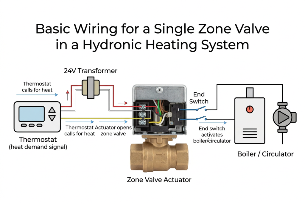
Putting It All Together: A Typical Wiring Schematic
Understanding how the actuator and end switch work in conjunction with other system components is best illustrated through a simplified electrical schematic. While specific wiring can vary between manufacturers and system complexities, the fundamental principles remain consistent.

Step-by-Step Electrical Flow:
- Power Supply: A low-voltage transformer (typically 24VAC) provides power to the control circuit. One side of the transformer connects to the common side of the thermostat and one side of the actuator.
- Thermostat Call: When the thermostat (e.g., ‘R’ to ‘W’ terminals) senses a call for heat, it completes the circuit, sending 24VAC to the actuator’s ‘power’ terminal (often red or yellow wire).
- Actuator Opens Valve: The actuator energizes and begins the process of opening the valve. During this phase, the end switch remains open.
- End Switch Engagement: Once the valve is fully open, the actuator mechanically closes the end switch (often two orange wires for common valves). This completes a separate circuit.
- Boiler/Pump Activation: The closed end switch sends a signal to the boiler’s control panel (e.g., ‘T’ terminals for heat demand), which then fires the boiler and/or engages the circulating pump to move hot water through the now-open zone valve.
- Thermostat Satisfied: When the zone reaches its set temperature, the thermostat opens its contacts, cutting power to the actuator.
- Actuator Closes Valve: The actuator de-energizes, and the valve body closes (often assisted by a spring return). As it closes, the end switch opens, signaling the boiler/pump to shut down for that zone.
Mastering these connections is vital for proper system operation. For detailed, step-by-step wiring instructions, refer to our guide: How to Wire a Zone Control Valve: A Technician’s Guide.
Common Issues Related to Actuators and End Switches
While robust, actuators and end switches are common points of failure over time, especially with frequent cycling. Recognizing their symptoms is key for effective troubleshooting:
- Stuck Open/Closed Actuator: Zone constantly heats/cools, or never heats/cools.
- Broken End Switch: Thermostat calls for heat, actuator opens valve, but boiler/pump never kicks on, leading to no heat in the zone.
- Noisy Actuator: Grinding sounds from motor-driven types could indicate gear wear.
Diagnosing these issues requires a systematic approach. When a zone isn’t heating or cooling correctly, the valve is a primary suspect. Learn how to diagnose the issue with our detailed guide: Field Guide to Troubleshooting Zone Control Valve Failures.
Conclusion: The Precision Behind the Performance
The seamless operation of a hydronic zone system hinges on the precise coordination between the actuator and the end switch within each zone control valve. This intricate electro-mechanical dance ensures that heating or cooling is delivered effectively, efficiently, and exactly where it’s demanded. For HVAC professionals, a deep understanding of these components is not merely academic; it’s fundamental to accurate diagnosis, effective maintenance, and optimal system performance.
At BCST Valve, we engineer our zone control valves with this precision and reliability in mind, ensuring that every actuator and end switch performs consistently under the rigorous demands of modern HVAC systems. Trust BCST for components that truly make your multi-zone system work.
Ready to enhance your hydronic system’s control and efficiency?


 English
 Arabic
 Russian
 French
 Spanish