
The 7 Technical Steps
In the high-stakes world of industrial fluid control, especially within fuel systems, specifying the correct valve is not just about functionality—it’s about ensuring safety, preventing costly downtime, and protecting your bottom line. A single miscalculation in a 3-ходовой шаровой кран specification can lead to pump dead-heading, cross-contamination, dangerous leaks, or inefficient operations that erode profits.
This comprehensive technical checklist is meticulously designed for industrial buyers, engineers, and facility managers. It distills years of practical experience into 7 essential steps, ensuring your valve meets every operational, safety, and material standard *before* you place an order. Utilize this guide as your definitive industrial valve buyer’s guide to avoid common pitfalls and optimize your system performance.
For a deeper understanding of these versatile components, we recommend consulting our 3-Way Ball Valve Comprehensive Guide.
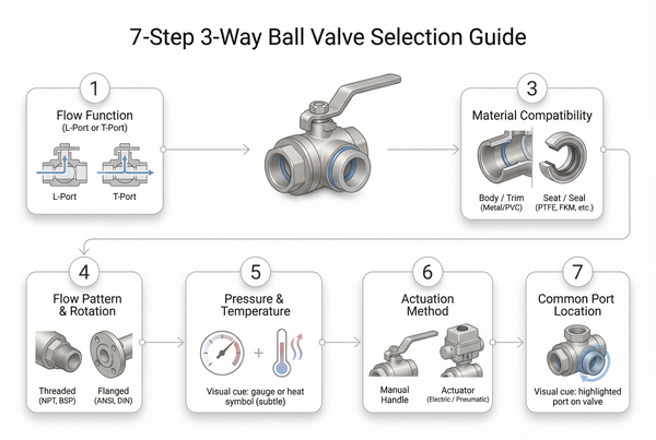
Step 1: Define the Primary Flow Function (L-Port vs. T-Port)
Diverting Flow (L-Port): When to choose a diverter for dual-tank distribution.
Determine if your application requires the fluid flow to be switched from one inlet to one of two outlets, or vice-versa. If you need to switch sources to different destinations (e.g., filling one of two tanks from a single supply line or selecting one of two pumps), then an L-Port configuration is the correct choice. It acts as a dedicated diverter or selector valve.
Mixing and Bypass (T-Port): Using T-ports for blending fluids or system recirculation.
If your system requires combining two different fluid sources into one outlet (mixing), or if you need a specific type of bypass that allows straight-through flow while also diverting, a T-Port valve is more appropriate. T-Ports offer greater versatility but understanding their exact internal flow paths is crucial. This is key for applications like blending fuel additives or creating recirculation loops.
Pro Tip 1: The “Function First” Rule
Never assume a T-Port can do everything an L-Port can. While a T-Port is more versatile, it often lacks a “center-off” position where all ports are completely sealed. If your safety protocol requires a position where all flow is blocked, you must verify if your specific 3-way ball design allows for a 180° turn to a non-bored section of the ball. Otherwise, external shut-off valves may be necessary.
Step 2: Verify Flow Pattern and Handle Rotation
Clearing the Swing Path: Planning for 90° vs. 180° handle clearance.
Manual 3-way valves require space for the handle to rotate. An L-Port typically rotates 90° to switch between its two operational positions. Some T-Port configurations may require a 180° turn to access all possible flow paths. Assess your system’s physical layout to ensure there’s adequate clearance for full rotation, especially in confined spaces or integrated into complex fuel manifold системы.
The Full Shut-Off Requirement: Warning about T-port limitations for 100% closure.
Некоторые T-Port valves, depending on their specific bore design, may not have a true “center-off” or “all ports closed” position. This means that at least two ports will always be connected, or one port will remain open. If your application mandates a full shut-off (100% closure of all flow), confirm the specific valve design allows for it, or plan for an additional shut-off valve upstream or downstream.
Pro Tip 2: Plan for Actuator Clearance
When determining handle swing or привод клапана space, remember that automated electric actuators are significantly bulkier than manual handles. Always calculate “Envelope Dimensions”—the total cubic space the valve and actuator occupy—to ensure you have room for safe maintenance access and proper wiring conduits in tight fuel manifolds and congested piping areas.
Step 3: Material Compatibility for Body and Seals
Stainless Steel Grades (316 vs. 304): Corrosion resistance in fuel environments.
For demanding fuel industry environments, нержавеющая сталь is the preferred body material. 304 Stainless Steel offers good general corrosion resistance, but Нержавеющая сталь 316 (or 316L for welding) contains molybdenum, providing superior resistance to pitting and crevice corrosion, especially when handling various fuels, their additives, or marine environments. Always choose 316/316L for critical and harsh applications.
Seat and O-Ring Materials: Choosing between PTFE и Viton/FKM.
The soft seals are critical for tight shut-off. PTFE (тефлон) offers excellent chemical resistance across a broad temperature range and is standard for many applications. However, for high-temperature fuel, oil applications, or aggressive chemical additives, Viton (FKM) provides superior performance in terms of chemical resistance and heat tolerance. Always verify the compatibility of your chosen seal materials with your specific media and operating temperature range to prevent degradation and leaks.
Pro Tip 3: Don’t Skimp on Seat Material
In the fuel industry, “Standard PTFE” is often not enough. If your media includes specific fuel additives, high-pressure steam cleaning cycles, or sustained high temperatures, specify Reinforced PTFE (RPTFE) или Viton (FKM) O-rings and seats. A $5 savings on a seal today can lead to a $5,000 environmental cleanup tomorrow if the seal degrades rapidly under chemical stress at elevated temperatures.
Step 4: Confirm Pressure and Temperature Ratings
Calculating the Flow Coefficient ($C_v$): Ensure the valve doesn’t choke your system.
Сайт Flow Coefficient ($C_v$) is a crucial metric that describes how much fluid will pass through a valve at a given pressure drop. Calculating the required $C_v$ ensures the valve’s internal bore doesn’t create excessive pressure drop or “choke” your system, affecting pump efficiency and flow rates. Always size your valve to achieve optimal flow with minimal energy loss. For accurate results, especially with non-water fluids, consider the fluid’s specific gravity.
Technical Formula Box: Calculating Flow Rate (Q)
$$Q = C_v \sqrt{\frac{\Delta P}{G}}$$
- Q: Flow Rate (GPM for US, m³/h for metric)
- $C_v$: Valve Flow Coefficient
- $\Delta P$: Pressure Drop across valve (PSI for US, bar for metric)
- G: Specific Gravity of Fluid (water = 1)
Maximum Operating Pressure (MAWP): Verification against industrial standards.
The chosen 3-way valve must meet or exceed the maximum system pressure. Standard industrial ball valves often meet ratings like 1000 PSI / 69 bar (WOG), but it’s crucial to cross-reference this with your actual system design pressure. Additionally, always consider the manufacturer’s pressure-temperature (P-T) curve, as the maximum allowable working pressure can decrease significantly at elevated temperatures.
Pro Tip 4: Account for Viscosity in $C_v$
The standard $C_v$ formula assumes water-like viscosity. If you are pumping heavy fuel oils (e.g., bunker fuel, crude oil) or high-viscosity lubricants, your actual pressure drop ($\Delta P$) will be significantly higher than the formula suggests, potentially throttling your flow. Always consult an extended $C_v$ table for viscous fluids or increase your valve size by one nominal increment if your fluid’s centipoise (cP) rating is notably high, to compensate for friction losses.
Step 5: Choose the Correct End Connection Type
NPT vs. Flanged vs. True Union: Selecting based on pipe size and maintenance.
- NPT Threaded: Standard for smaller industrial lines (typically 2 inches and below) where quick, leak-tight connections are sufficient, often used for utility or non-critical lines.
- Flanged (ANSI/DIN): Required for high-pressure, large-diameter fuel manifolds, or applications where robust, easily verifiable, and often bolted connections are necessary. Ensures high integrity and simplifies removal for major overhauls.
- True Union: Ideal when the valve body needs frequent removal for cleaning, inspection, or seat replacement without disturbing the surrounding inline piping. This is invaluable for systems handling solids, slurries, or “sticky” media. For assembly tips, see our guide on True Union Ball Valve Installation.
Pro Tip 5: The “True Union” Maintenance Hack
If you choose a True Union end connection for a system that handles “sticky” media (like crude oil or certain fuel additives), install the valve with enough “pipe play” or flexible connectors to allow the union nuts to slide back fully. If the pipe is rigid and anchored too close to the valve, you won’t be able to slip the valve body out for cleaning, defeating the primary purpose and maintenance benefits of the union design.
Step 6: Define Automation and Actuation Needs
ISO 5211 Mounting Pads: Ensuring the valve is “automation-ready.”
If there’s any possibility of automating the valve in the future, specify a 3-way ball valve with an ISO 5211 mounting pad. This international standard ensures that electric or pneumatic actuators can be easily and directly mounted, providing a seamless upgrade path without replacing the entire valve. This future-proofing saves significant time and cost down the line. For more on this, see our article on Manual vs. Electric 3-Way Ball Valves.
Breakaway Torque: Calculating the force needed to turn the valve under full pressure.
For automated systems, the actuator’s torque output must exceed the valve’s breakaway torque—the initial force required to unseat the ball and initiate rotation. This force is often much higher than the running torque, especially when the valve has been closed under full system pressure or exposed to viscous media for an extended period. Always factor in a safety margin when determining torque requirements to prevent actuator motor burnout.
Pro Tip 6: Calculate “Breakaway Torque” Correctly
A valve that turns easily on a workbench (without process pressure) will require 20-30% more torque once it is under full system pressure and has been sitting in one position for a month, allowing media deposits or thermal expansion to increase friction. When sizing an electric actuator, always add a **25% Safety Factor** to the manufacturer’s published valve seating torque rating to ensure the motor doesn’t burn out during a cold start or emergency actuation. This is especially true for valves in remote fuel systems where manual intervention isn’t immediate.
Step 7: Identify the Common Port Location
Bottom Entry vs. Side Entry: Matching the valve hub to your piping manifold layout.
Сайт common port is typically the primary inlet or outlet. Industrially, it’s most often located at the bottom (also known as “bottom entry”) of the valve body, with the two side ports feeding in or out from the sides. However, some manufacturers offer “side entry” common ports. Ensure your selected valve’s common port orientation matches your piping manifold layout to prevent complex bends or flow inefficiencies. Visual confirmation with the manufacturer’s diagram is critical.
Preventing Pump Damage: Why the “AB” port orientation is critical.
Correct alignment of the common port ensures that the flow paths (often labeled A, B, and AB or C) are correctly routed as intended by the system design. Incorrect orientation can lead to unintended flow paths, potentially “dead-heading” pumps (blocking discharge flow), causing back pressure, or mixing incompatible fluids. Always verify the manufacturer’s port labeling and ensure it aligns with your system engineering documents to avoid catastrophic failures or safety incidents in hazardous fuel systems.
Pro Tip 7: Mark Your Common Port Physically
Even if the manufacturer labels the ports A, B, and AB, use a permanent paint pen or a highly visible tag to mark the Common Port (e.g., “Main Inlet”) on the valve and connecting pipe itself during installation. This crucial step prevents future maintenance crews from reinstalling the valve 90° or 180° out of phase, which is one of the most common causes of pump failure, cross-contamination, or unexpected flow in 3-way systems—a particularly dangerous oversight in fuel manifold distribution.
Frequently Asked Questions (FAQ)
Q: What is the most common mistake when buying a 3-way valve?
The most common and impactful mistake is choosing the wrong port configuration—an L-Port when a T-Port is needed, or vice-versa. This fundamentally dictates the possible flow paths and can lead to incorrect mixing, diverting, or bypass operations, causing inefficiencies, equipment damage, or compromising safety, especially in critical fuel systems.
Q: Can I automate a 3-way valve later?
Yes, it is often possible to automate a 3-way valve later, provided it was initially specified with an ISO 5211 mounting pad. This industry-standard interface allows for direct attachment of pneumatic or electric actuators. Without this pad, retrofitting can be complex, costly, or simply infeasible. Always plan for potential future automation needs at the specification stage.
Q: How do I calculate the pressure drop across a 3-way valve?
You can calculate the pressure drop ($\Delta P$) across a 3-way valve using its Flow Coefficient ($C_v$) and the fluid’s specific gravity (G) with the formula: $Q = C_v \sqrt{\frac{\Delta P}{G}}$. You’ll need to rearrange the formula to solve for $\Delta P$ and input your known flow rate (Q) and specific gravity. Always ensure the calculated $\Delta P$ is within acceptable limits for your system design and pump capabilities, especially considering fluid viscosity for heavy oils.
Conclusion: Final Verification Before Ordering
For a fuel industry facility manager, the value of accurately specifying a 3-way ball valve through a rigorous checklist is not just about avoiding immediate problems; it’s about significant, long-term Return on Investment (ROI). Precision at the specification stage directly translates into:
- Reduced Downtime: A correctly specified valve performs reliably, minimizing unexpected failures and the associated production losses. Each hour of unplanned stoppage can cost thousands.
- Повышенная безопасность: With hazardous fuels, preventing leaks, improper mixing, or pump damage through perfect valve selection is a non-negotiable safety mandate, protecting personnel and environmental integrity from catastrophic risks.
- Lower Operational Costs: Optimal flow characteristics (correct $C_v$) reduce energy consumption from pumps. Longevity from compatible materials means fewer replacements, less maintenance, and sustained performance.
- Future-Proofing: Features like ISO 5211 mounting pads facilitate future upgrades to electric 3-way ball valve automation without incurring prohibitive rip-and-replace costs, ensuring your infrastructure adapts to evolving industry demands.
This checklist is your proactive shield against costly oversights. Take the time to apply these 7 technical steps, and you’ll safeguard your operations, improve efficiency, and secure your investment for years to come.
Ready to verify your specifications or need expert assistance?


 English
 Arabic
 Russian
 French
 Spanish