
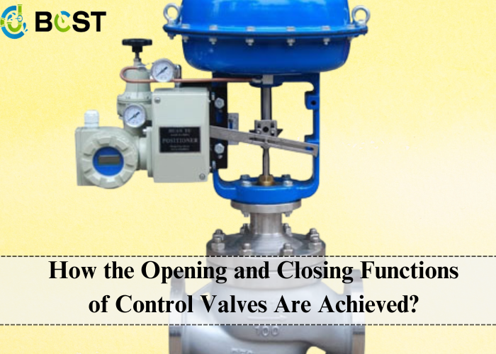
In the realm of industrial automation control, control valves serve as pivotal control elements, widely employed across various industries such as petroleum, chemicals, power, metallurgy, pharmaceuticals, and food processing. Their precision control is paramount to ensuring smooth process flows, enhancing production efficiency, and improving product quality. As a professional manufacturer, we deeply understand the significance of precise control by control valves in maintaining industrial processes. This article delves into the fundamental principles, classifications, structures, and mechanisms underlying how the opening and closing functions of control valves are realized.
I. Fundamental Principles of Control Valves
Control valves regulate fluid media’s flow rate, pressure, and temperature. They work based on fluid mechanics and control theory, adjusting the flow rate by altering the valve’s opening to precisely control fluid systems. The opening and closing functions of control valves, essentially, involve manipulating the relative position between the valve trim and valve seat to control the flow area, thereby regulating fluid flow rate, pressure, and temperature parameters.
II. Classifications of Control Valves
Control valves can be categorized into several types based on their structures and working principles, each with unique applications and advantages:
1. Straight-Through Control Valves
- Characteristics: The valve trim is parallel to the valve seat, allowing fluid to enter from one side of the valve body and exit from the other. They are known for their simplicity, ease of maintenance, and versatility.
- Applications: Widely used in fluid control systems across industries, particularly suitable for scenarios with no specific flow direction requirements.
2. Angle-Pattern Control Valves
- Characteristics: The valve trim is perpendicular to the valve seat, enabling fluid to enter from one side and exit from the other. They offer compact designs, low fluid resistance, and quick response times, ideal for applications with specific flow direction requirements.
3. Plug Control Valves
- Characteristics: The valve trim is cylindrical, rotating to regulate fluid flow. They exhibit low fluid resistance, high control accuracy, and strong adaptability.
- Applications: Commonly used in petroleum, chemicals, and power industries, particularly suited for high-precision flow control scenarios.
4. Butterfly Control Valves
- Characteristics: The valve trim is disk-shaped, rotating to regulate fluid flow. They are structurally simple, small in size, and lightweight, ideal for small to medium-sized flow control systems.
5. Ball Control Valves
- Characteristics: The valve trim is spherical, rotating to control fluid flow. They boast simple structures, excellent sealing performance, and strong corrosion resistance, making them suitable for high-temperature, high-pressure, and corrosive media control.
6. Gate Control Valves
- Characteristics: The valve trim is a flat plate, moving vertically to regulate fluid flow. They feature simple structures, good sealing performance, and high wear resistance, ideal for handling particulate media and high-viscosity fluids.
III. Structures and Components of Control Valves
Control valves primarily consist of valve bodies, valve trims, valve seats, valve stems, and actuators. These components work in harmony to realize the opening and closing functions.
1. Valve Body
- Role: The main structure of the control valve, housing the flow path aligned with the media flow direction. It connects to the valve seat and trim.
- Requirements: The material and manufacturing process must meet the media’s characteristics and operational environment to ensure strength and sealing.
2. Valve Trim and Seat
- Role: The valve trim is the crucial component that controls the flow area by adjusting its position relative to the valve seat. The seat provides a sealing surface for the trim.
- Requirements: The trim and seat materials must exhibit good wear resistance, corrosion resistance, and sealing capabilities to ensure reliability and stability.
3. Valve Stem
- Role: Connects the valve trim to the actuator, transmitting the actuator’s driving force to the trim for reciprocating motion.
- Requirements: The stem must possess high rigidity and wear resistance to withstand media pressure and actuator forces.
4. Actuator
- Role: The driving mechanism of control valves, receiving control signals to move the valve stem and trim, opening or closing the valve.
- Types: Depending on the power source, actuators can be manual, electric, pneumatic, or hydraulic, each with distinct characteristics and applications.
IV. Realization of Opening and Closing Functions
The realization of control valves’ opening and closing functions primarily depends on the actuator type and control signal input. Here are the mechanisms for common actuator types:
1. Manual Control Valves
Realization: The valve trim’s position is adjusted manually through a knob or handle, regulating the valve opening. They are simple to operate but offer low automation levels, suitable for non-critical automation requirements.
2. Electric Control Valves
Realization: Electric actuators change the valve trim’s position upon receiving control signals. The actuator drives the valve stem and trim, adjusting the valve opening with high precision and fast response times. Widely used in industrial automation systems due to their high automation levels and accuracy.
Key Technologies: Proper actuator selection aligned with pipe diameter and flow requirements; precise manufacturing of valve bodies and seats for accurate flow area control; advanced control algorithms and sensor technologies for optimization.

3. Pneumatic Control Valves
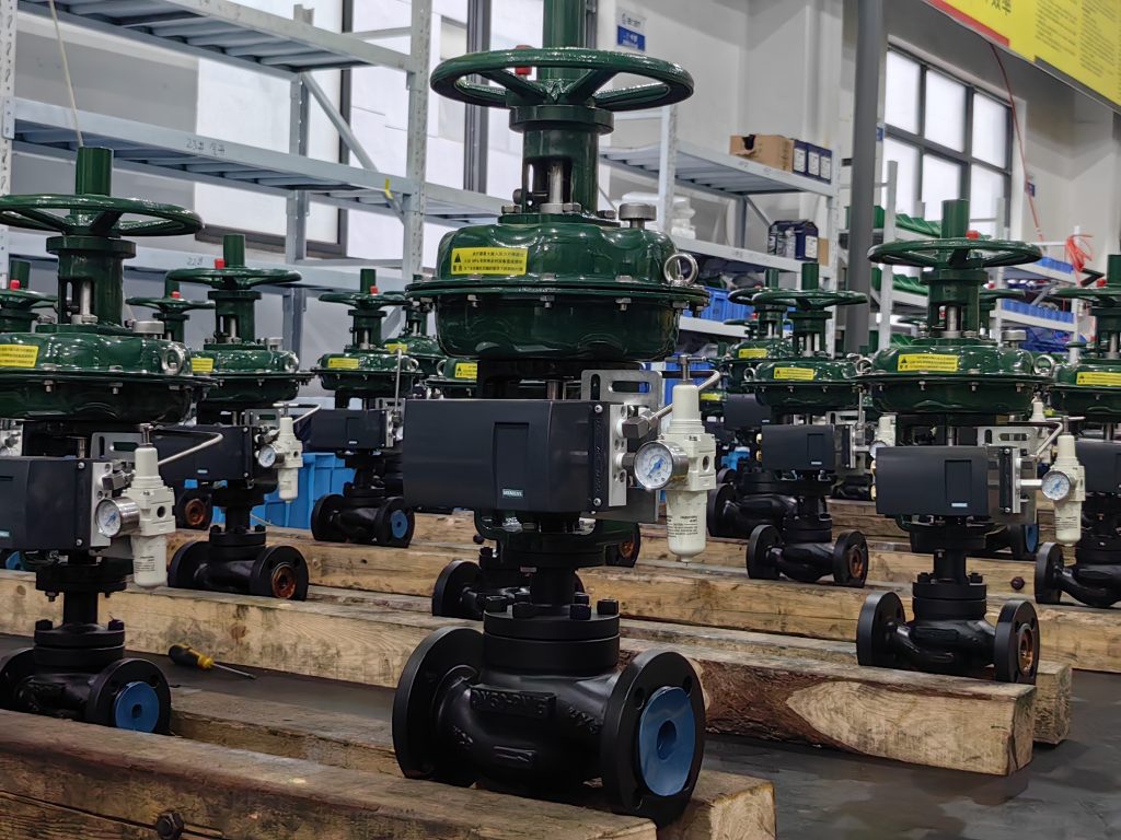
Realization: Pneumatic actuators use compressed air to move pistons or diaphragms, driving the valve stem and trim. When compressed air enters the actuator, it pushes the piston or diaphragm, opening or closing the valve. Known for their reliability, simplicity, and ease of maintenance, especially suitable for flammable, explosive, or corrosive media.
Working Principle: In pneumatic diaphragm actuators (as an example), compressed air enters the actuator, pushing against springs and gravity to close the valve. An electrical signal or actuator action opens the valve, allowing full flow. Without the signal or action, the valve remains closed.
4. Hydraulic Control Valves
Realization: Hydraulc actuators leverage fluid pressure differences to move pistons or diaphragms, driving the valve stem and trim. They offer strong driving forces and smooth operation, ideal for large-diameter, high-differential pressure media control.
V. Conclusion
Control valves, as vital execution elements in industrial automation control, employ diverse mechanisms to achieve their opening and closing functions, primarily determined by actuator types and control signal inputs. Whether manual, electric, pneumatic, or hydraulic, each type boasts unique characteristics and applications. As a professional manufacturer, we strive to provide high-quality, high-performance control valve products to meet the fluid control needs of various industries and operating conditions. Furthermore, we continuously innovate and improve our technologies to drive the continued advancement and development of control valve technology.


 English
 Arabic
 Russian
 French
 Spanish