

Many industrial facilities install turbine fire pumps, but few people truly understand how the system components—especially jockey pumps and foot valves—work together. If you don’t know their roles, you may face pressure loss, failure to start, or delayed response during emergencies.
A turbine fire pump system works by drawing water from a below-grade source through a foot valve, pressurizing it via a vertical turbine pump, and using a jockey pump to maintain system pressure and prevent false starts.
This setup may sound complex, but when broken down step-by-step with a diagram, it’s easier to understand. Let me walk you through it, especially if you’re managing fire systems in high-risk industrial environments.
What Is The Role Of The Jockey Pump In A Turbine Fire Pump System?
Jockey pumps are often misunderstood, yet they are critical for smooth fire system operation. They maintain pressure and reduce the load on the main turbine pump.
The jockey pump maintains the fire system’s pressure during minor leaks or temperature changes, preventing the main pump from cycling on unnecessarily.
Without the jockey pump, every small pressure drop would activate the turbine pump, leading to early wear or system failure. Here’s a clearer breakdown:
How It Works
- Normal State: The jockey pump keeps the system at the preset pressure (e.g., 120 psi).
- Leak or Temperature Drop: Small pressure drop occurs (e.g., 110 psi).
- Jockey Pump Start: It starts automatically, restoring pressure.
- Fire Situation: When pressure drops sharply (e.g., 60 psi), only then does the turbine pump activate.
| Component | Function |
| Jockey Pump | Maintains static system pressure |
| Pressure Switch | Senses drops, controls pump start/stop |
| Controller | Coordinates with turbine pump logic |
What Is The Function Of A Foot Valve In Vertical Turbine Pumps?
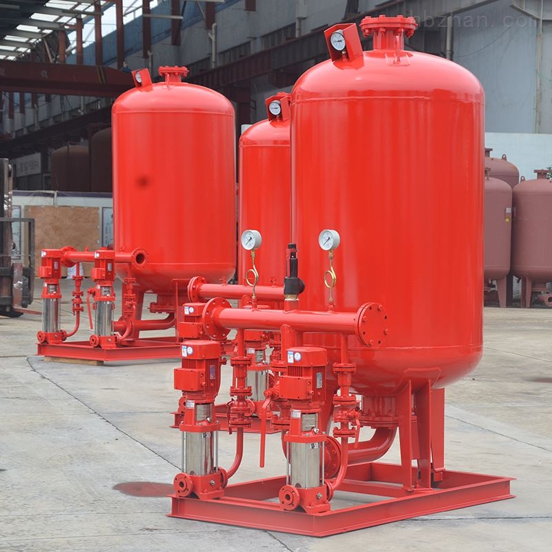
When using a turbine fire pump, the foot valve plays a silent but vital role. It prevents water from draining back down, keeping the system ready for action.
The foot valve ensures water stays inside the suction pipe, allowing the turbine fire pump to start immediately without needing to be primed.
If the foot valve leaks, air enters the suction line. That means longer priming time—or worse, no water during a fire. Here’s how it works in detail:
Why Foot Valves Are Critical
- One-Way Flow: Foot valves are check valves at the suction end.
- Priming Stability: Keeps the pump primed, especially for deep wells or tanks.
- System Readiness: Guarantees water is available instantly when turbine pump starts.
| Issue | Result |
| Foot valve failure | Backflow, air in line, delayed priming |
| No foot valve | Pump cannot self-prime |
| Proper foot valve | Immediate water draw on pump start |
How Does A Complete Turbine Fire Pump Diagram Look?

Understanding the whole system layout helps avoid installation errors. The diagram shows how the pump, jockey pump, and foot valve are connected.
The standard turbine fire pump diagram includes a water source, vertical turbine pump with foot valve, discharge piping, jockey pump with pressure switch, and fire control panel.
This system is built for vertical lift and constant readiness. Key parts include:
Main Components In The Diagram
- Water Source (underground tank or well)
- Foot Valve (at the suction end of vertical pipe)
- Vertical Turbine Pump (multi-stage, motor-driven)
- Check Valve & Isolation Valve (on discharge line)
- Jockey Pump (small horizontal pump)
- Pressure Sensors (for both jockey and main pump)
- Controller Panel (manages operation logic)
Roles Of Jockey Pump, Foot Valve, Maintenance Issues, And Installation Tips
Turbine fire pumps are widely used in industrial fire protection systems, especially in high-risk environments. They are often paired with jockey pumps and foot valves to ensure the system operates reliably and efficiently. However, many people do not fully understand how these components work together or the potential risks caused by poor maintenance or improper installation. In this article, I will walk you through the full working principle, key components, system structure, maintenance challenges, and practical installation recommendations.
The core working principle of a turbine fire pump system is to draw water from a below-ground source through a foot valve, pressurize it via a vertical multistage pump, and then discharge it into the fire suppression piping system. The jockey pump plays the role of maintaining system pressure during non-emergency situations to prevent the main pump from starting unnecessarily.
What Are The Most Common Maintenance Issues With Jockey Pumps And Foot Valves?
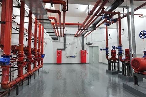
Even with the best equipment, poor maintenance can lead to performance issues. Here are the most frequent maintenance problems I’ve encountered:
Jockey pump problems:
- Seal or gasket leaks due to aging or low-quality materials.
- Motor overheating caused by poor ventilation or overload.
- Pressure switch miscalibration due to vibration or incorrect manual settings.
- Control circuit corrosion, especially in humid or underground rooms.
Foot valve issues:
- Seal failure from debris, corrosion, or wear.
- Blockage or jamming from sand or rust.
- Backflow due to air leaks or cracked housing.
- Suction delays from a clogged intake screen.
To maintain reliability:
- Test jockey pump operation monthly and observe system pressure recovery.
- Inspect for leaks or unusual sounds around the pump base.
- Pull and clean the foot valve every 6–12 months.
- Use non-corrosive materials like stainless steel or bronze for harsh environments.
Key Installation Tips For A Turbine Fire Pump System
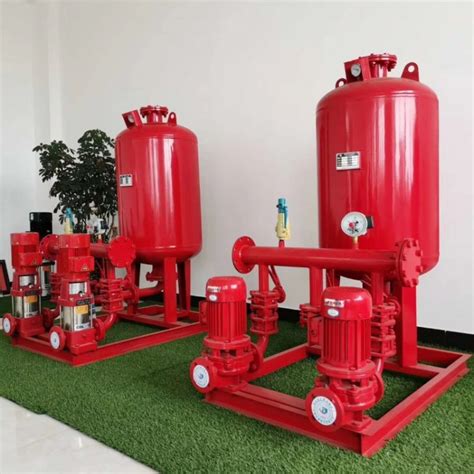
Installing a turbine fire pump system is not just about connecting pipes and wires. Each component must be placed with long-term performance in mind. Here are my top installation recommendations:
- The foot valve must always be fully submerged below the lowest expected water level. In sites with fluctuating water levels, install a low-level alarm and extend the suction pipe to avoid air intake.
- Avoid “U” shapes or poorly sloped drain piping, which can trap air pockets. Install air release valves at high points to prevent pressure fluctuations.
- Calibrate pressure switches during commissioning. A typical setting is 120 psi static pressure, jockey pump on at 110 psi, and turbine pump on at 60 psi. This helps reduce false starts.
- Position the jockey pump as close as possible to the main header to reduce pressure drop and avoid delay in sensing pressure changes.
- Use flexible connectors and anti-vibration pads between the pump and piping, especially for vertical turbine pumps, which generate axial vibration during start/stop.
- Keep the control cabinet dry, well-ventilated, and installed away from the pump base or water sources. In underground pump rooms, raise cable trays and use waterproof enclosures to protect electrical systems.
Conclusion
The reliability of a turbine fire pump system depends on the precise coordination of all its components. The jockey pump maintains standby pressure, the foot valve ensures suction integrity, and the turbine pump delivers water during emergencies. Only by selecting the right equipment, installing it correctly, and performing regular maintenance can we ensure the fire system responds properly when it’s needed most.
If you need help with selecting the right configuration, reviewing diagrams, or preparing a site-specific solution, feel free to reach out to me.


 English
 Arabic
 Russian
 French
 Spanish