
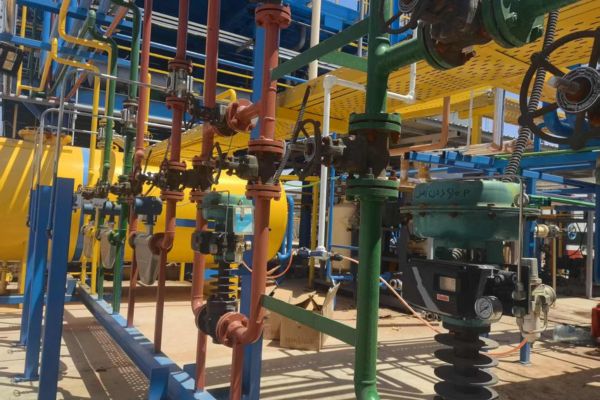
In chemical processing plants, stable airflow and precise flow control are essential for ensuring that critical processes—such as combustion, aeration, and gas purging—operate reliably. Plant managers and engineers often ask, “Where is the idle air control valve located?” Although this term is more common in automotive settings, in industrial chemical systems it refers to control valves dedicated to maintaining precise airflow during low-load or idle conditions.
In chemical process systems, idle air control valves are typically installed near air delivery points. They are commonly found upstream of burners, close to aeration diffusers, or at the inlet of gas purging lines. Their precise placement ensures that even under low-demand conditions, the necessary minimum airflow is maintained to keep processes stable and efficient.
Understanding the exact location, function, and selection criteria for these valves is critical. Not only does it help prevent system downtime, but it also improves energy efficiency and process safety. In this article, I will explore the role of idle air control valves in chemical systems, share a real-world case study, and offer practical guidelines for installation and maintenance—all optimized for search engines to help you find the solutions you need.
What Is an Idle Air Control Valve in Chemical Process Systems?
Idle air control valves in the chemical industry are not standalone components; rather, they represent a functional requirement within a control valve system. Their purpose is to regulate airflow during periods when the process operates below full capacity. This is especially important in applications such as:
- Combustion systems: Where maintaining a consistent air-to-fuel ratio at low loads prevents flame instability.
- Aeration in bioreactors or wastewater treatment plants: Where constant low airflow supports biological processes.
- Gas purging in reactors and storage tanks: Where a minimal but constant flow of inert or process gases prevents contamination or unwanted reactions.
The idle air control valve operates by receiving control signals—usually from a distributed control system (DCS) or programmable logic controller (PLC)—to modulate its opening and thereby adjust the airflow rate to meet process requirements.
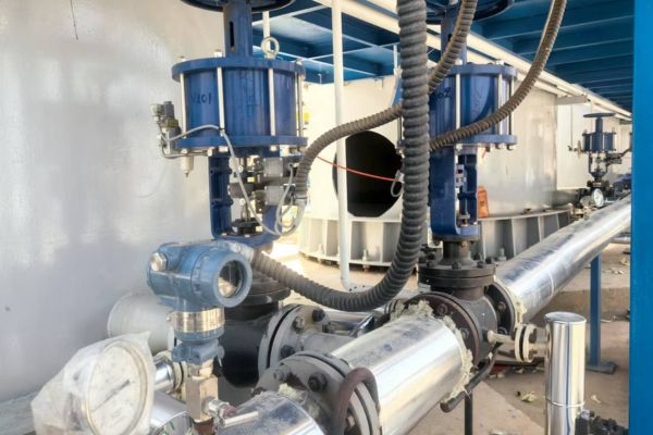
The Critical Role of Idle Air Control in Chemical Plants
Maintaining precise airflow under idle or low-load conditions is essential for several reasons:
- Process Stability: In combustion systems, too little air can cause incomplete combustion, leading to carbon buildup and potential safety hazards. Conversely, too much air may lead to inefficient fuel use.
- Efficiency: Optimized airflow ensures that energy is not wasted during periods when full capacity is not needed.
- System Protection: Idle air control helps prevent system stagnation and maintains the necessary conditions for downstream equipment.
For example, in one of our projects, a chemical plant experienced frequent shutdowns of its burner system during off-peak hours. The issue was traced back to improper airflow regulation. By fine-tuning the control valve settings and relocating the valve closer to the burner inlet, the plant achieved significant improvements in process stability and fuel efficiency.
Typical Installation Locations for Idle Air Control Valves
Determining the best location for an idle air control valve depends on the specific process and system layout. In chemical plants, these valves are strategically placed to ensure that they can accurately modulate airflow even under low load.
Typical examples include:
- Burner Air Control Systems: Just upstream of the burner, where air mixes with fuel. The valve ensures that the burner receives a steady and precise amount of air during start-up, shutdown, and low-load operation.
- Reactor Gas Purge Lines: At the inlet of the nitrogen or inert gas feed line. The valve maintains a consistent flow of purge gas to prevent the buildup of unwanted chemical species.
- Aeration Systems: On branch lines leading to aeration diffusers or headers. The valve regulates the minimal airflow required to support microbial activity and ensure proper oxygenation.
- Inert Blanketing: At the top nozzle where inert gases like nitrogen or CO₂ are introduced. The valve ensures that a protective gas layer is maintained to prevent oxidation or contamination.
Which Valve Types Are Ideal for Idle Air Control?
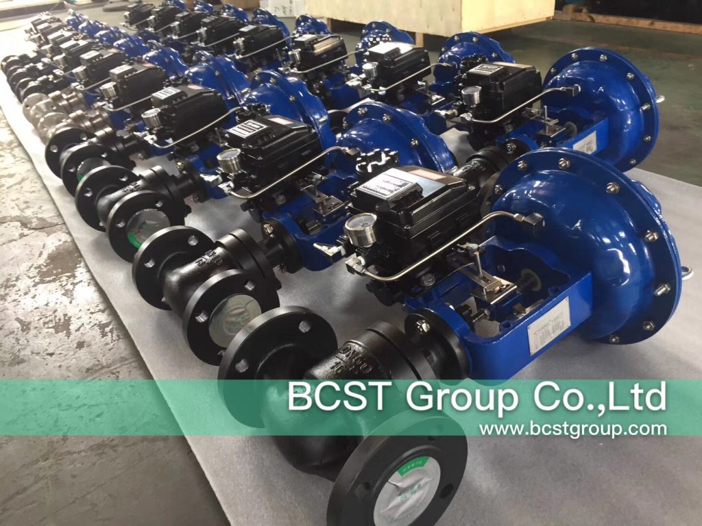
Not all valves perform well at low-flow conditions. It is essential to choose valve types that offer precise control and stability during idle operation. Recommended valve types include:
Pneumatic Globe Valves
- Excellent control at low flows with a linear characteristic
- High precision and ease of integration
- Ideal for burner air control and reactor purge systems
V-Notch Ball Valves
- Good control rangeability with compact design
- Suitable for both air and inert gas
- Common in blanketing and purge lines
Diaphragm Valves
- Ideal for clean air and low-noise operation
- Smooth flow adjustment
- Good for bioreactors or aeration systems
Butterfly Valves
- Less accurate at very low flow
- Affordable and lightweight
- Used in less critical airflow systems
Energy Savings Estimation: How Much Can You Save by Optimizing Idle Air Control?
Even small inefficiencies in airflow control during idle periods can add up to significant energy waste—especially in systems running 24/7.
Let’s break it down with an example.
Case Example: Burner Idle Air Optimization
- System: Natural gas burner in a chemical heater
- Previous idle airflow: 20 Nm³/h (too high)
- Optimized airflow: 12 Nm³/h (post valve upgrade)
- Burner operating idle: 10 hours/day
- Air compression cost: ~0.06 USD per Nm³
- Days per year: 300
Annual Savings = (20 – 12) × 10 × 0.06 × 300 = $1,440/year (per unit)
Now, multiply this by 5–10 similar units in a plant and you’re looking at $7,000–15,000 in compressed air savings annually—without touching the main production output.
If fuel efficiency is also improved due to better air/fuel ratios, the additional savings from reduced gas consumption can be 2–5x higher.
Additional Benefits:
- Shorter startup time due to stable idle conditions
- Lower maintenance frequency on burners or blowers
- Reduced CO₂ emissions = easier environmental compliance
If you’d like us to run a custom ROI simulation for your plant based on air usage data, contact Emily at info@bcstgroup.com.
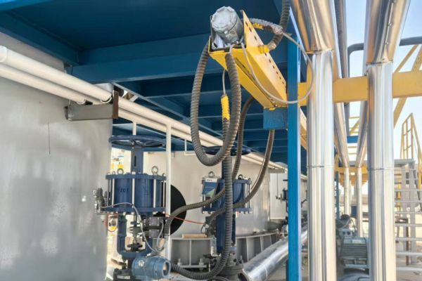
Control Valve Sizing Guidelines: How to Select the Right Size?
Proper valve sizing is critical to avoid:
- Oversized valves that “hunt” during low flow
- Undersized valves that cause pressure drop or choking
- Poor turndown ratio affecting idle control
To size a valve for idle air control, gather the following:
- Maximum and minimum flow rate (especially the idle flow)
- Line pressure (inlet and outlet)
- Media type (air, nitrogen, CO₂, etc.)
- Temperature (impacts flow density)
- Required control range (e.g., turndown ratio of 10:1)
General Rule of Thumb:
Design valve to operate at 30–70% open under idle conditions
Keep pressure drop (ΔP) within 10–30% of upstream pressure
Use equal-percentage trims for large turndown needs
Include a safety factor of 10–20% to account for process variability
BCST’s Engineering Support Includes:
- Software-based valve sizing using ISA formulas or industry tools
- Sizing reports with Cv values, flow curves, and trim selection
- Selection of matching actuators, positioners, and accessories
Just send us your datasheet or system diagram, and we’ll provide a complete valve sizing proposal within 1–2 working days.
Real-World Case Study: Hasan’s Experience
Hasan is the owner of a technical company in Iran specializing in oil and gas plant operations. His plant includes a steam reforming unit, which was frequently shutting down during idle operation—especially at night.
The Challenge: His team identified flame instability due to fluctuating airflow at low burner loads. The idle air control valve was installed far from the burner, causing delays in response.
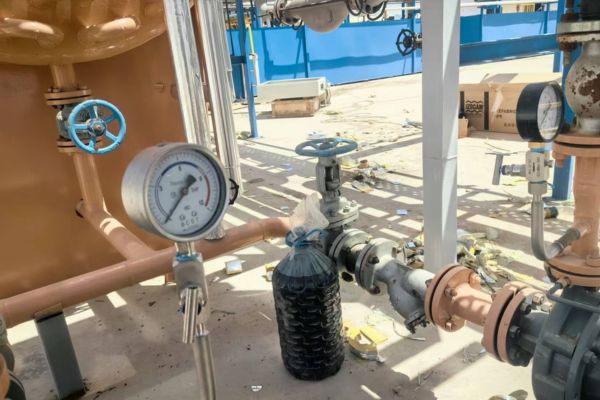
The Solution: We proposed moving the valve closer to the burner inlet and replacing it with a BCST pneumatic globe valve fitted with a digital positioner. This allowed for precise airflow control even at low volumes.
The Outcome:
- Stable burner operation
- 8% gain in combustion efficiency
- Over USD 22,000 saved annually in fuel costs
- Elimination of unplanned shutdowns
Installation and Commissioning Best Practices
To ensure smooth idle airflow control, follow these guidelines:
Before Installation:
- Analyze system airflow requirements
- Select a valve that supports precise low-flow modulation
- Survey location: keep valves close to the air delivery point
During Installation:
- Ensure minimal pipe distance between valve and process unit
- Install filters to protect the actuator
- Use bypass lines for maintenance access
Commissioning:
- Calibrate the valve and positioner accurately
- Test valve performance under idle and full-load conditions
- Integrate with DCS or PLC for continuous monitoring
- Train operators on valve operation and troubleshooting
Conclusion
Idle air control valves are essential for chemical plants to maintain stable operation during low-load conditions. Proper location—near burners, diffusers, or gas inlets—paired with the right valve type ensures efficient, safe, and cost-effective control.
At BCST, we help engineering teams worldwide select the right control valve for idle airflow, combustion control, and gas modulation. Whether you operate in oil refining, wastewater, fertilizer, or petrochemicals, we can deliver solutions that make a difference.
For expert support or custom valve consultation, contact Emily Xu at info@bcstgroup.com or visit www.bcstvalve.com


 English
 Arabic
 Russian
 French
 Spanish