

Your plant is down, alarms are blaring, and you suspect the worst. A total system crash. You’re confronting a nightmare scenario: one of the dreaded DCS failures in power plants.
Most DCS failures in power plants are not caused by the central controller. They often stem from field-level problems like faulty sensors, stuck final control elements (valves), or network communication breakdowns that mimic a catastrophic system crash and lead to costly downtime.
Before you assume your multi-million dollar control system is broken, you need to look closer. I’ve spent my life around industrial equipment, thanks to my father’s valve factory. And I’ve learned from the best, like my friend Hassan, a Chief Engineer who designs entire chemical plants. He says that the most dramatic DCS failures in power plants often start with the simplest components. Let’s break down where the real problems usually hide, so you can find them faster and get your plant back online.
Can a Single Faulty Sensor Mimic Major DCS Failures in Power Plants?
You see an erratic temperature reading on the screen. The system is unstable, and you assume the controller is broken. You are now preparing for a long and costly troubleshooting process.
Yes, a failing instrument is a primary cause. The sensor sends bad data to the DCS. The control system reacts to this false information, which can destabilize a process or trigger alarms, making it look exactly like one of the major DCS failures in power plants.
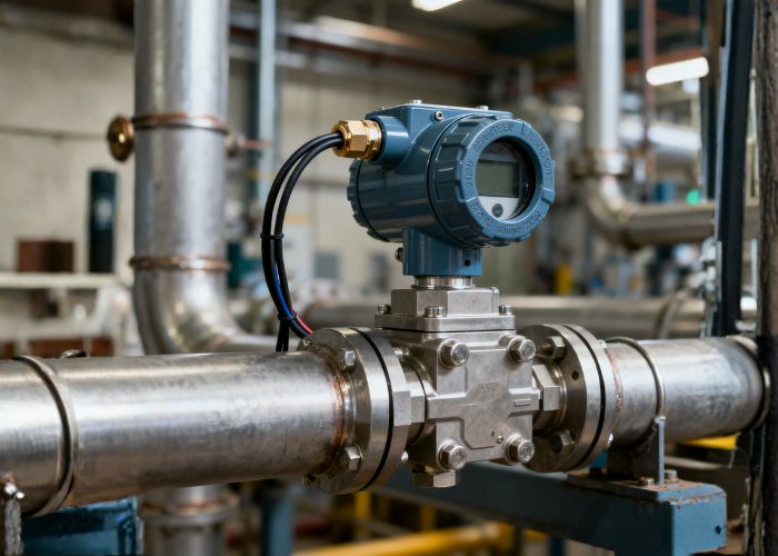
A control system is only as good as the information it receives. It is the classic "Garbage In, Garbage Out" problem. Hassan once shared a story about a client’s refinery. The operators were convinced their main reactor’s DCS controller had failed. The temperature reading was jumping wildly, causing the cooling system to overreact and making the whole process unstable. The plant manager was about to order a very expensive replacement controller module. Hassan flew in and insisted they start with the basics. His team traced the wiring from the controller all the way back to the reactor. They found the problem not in the control room, but out in the field. A simple temperature sensor’s connection box had water inside, causing corrosion on the terminals. This bad connection created the erratic signal. They cleaned the contacts and sealed the box. The problem disappeared. A fix that cost almost nothing saved them from a huge expense and days of downtime. This is a perfect example of how a simple sensor issue can masquerade as one of the most complex DCS failures in power plants.
How to Isolate the Real Problem
You must have a clear process to find the root cause. Instead of starting at the complex DCS, start where the data is created: the field instrument. This logical approach will save you hours of frustration. Your first step should always be to question the validity of the data the DCS is working with.
Here’s a simple table to guide your initial diagnosis:
| Observed Symptom | Most Likely Cause | First Diagnostic Step |
|---|---|---|
| One single measurement is frozen or erratic. | Instrument or Wiring Fault. | Physically inspect the sensor, its wiring, and its power supply. Use a multimeter to check the signal. |
| An entire group of instruments on one I/O card is offline. | DCS I/O Card Failure. | Check the status lights on the specific Input/Output card in the DCS cabinet. Verify its power. |
| An entire physical area of the plant is offline on the screens. | Network Switch or Local Power. | Check the network switch that serves that area. Confirm that the local power distribution panel for those instruments is on. |
| The entire control system is unresponsive. | DCS Server, Main Network, or Central Power Failure. | This is a true emergency. Initiate your plant’s specific protocol for total loss of control. This is a genuine, critical DCS failure. |
By following this logic, you methodically rule out the simple, more common problems first. This discipline is key to quickly resolving what appears to be serious DCS failures in power plants.
How Can a Stuck Valve Cause Catastrophic DCS Failures in Power Plants?
Your boiler pressure is rising fast. The DCS commands the steam vent valve to open, but the pressure keeps climbing. The system trips, forcing a total shutdown to prevent an explosion.
A stuck valve breaks the control loop. The DCS, which is the "brain," sends a command, but the valve, which is the "hand," does not respond. The system sees the process variable going critical and, unable to control it, will initiate a protective shutdown to keep the plant safe.
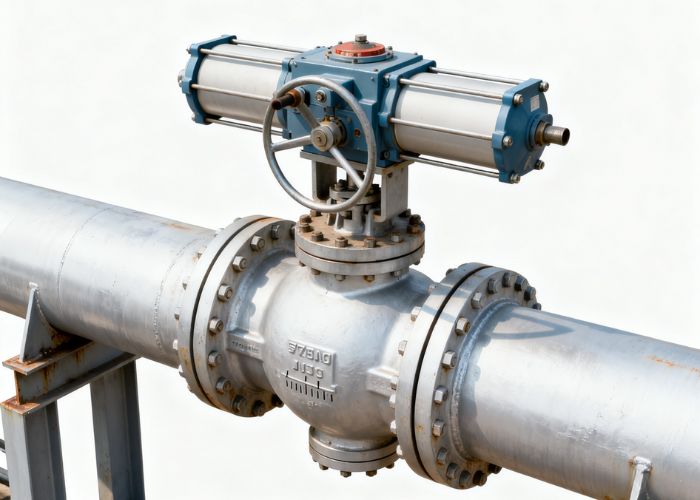
From my first days working on the floor of my family’s valve factory, I learned that a valve is a precision machine. When I later began visiting customer sites, I saw the real-world consequences when that machine fails. A client at a power station had a recurring problem where their main turbine would trip on overspeed. The DCS logs showed that the governor control valves were commanded to close, but the turbine speed kept increasing for a few critical seconds before the emergency trip. They spent weeks analyzing the DCS logic and controller tuning. I suggested they inspect the valves. When they pulled the large hydraulic actuators, they found that internal seals had degraded from contaminated hydraulic fluid. This caused the valves to respond very slowly—too slowly for the DCS to handle a sudden load rejection. The DCS was sending the right commands, but the physical hardware couldn’t keep up. This sluggish response from the final control element was the true root cause of what looked like one of the most dangerous DCS failures in a power plant.
Your Valves Are the Last Line of Control
The DCS can have the most advanced algorithms in the world, but if the valve at the end of the line doesn’t move correctly, the system is useless. This is why mechanical integrity is just as important as control logic for preventing DCS failures in power plants. You must see your valves and your DCS as one integrated system.
Here are the most common valve-related failures that can trigger a plant shutdown:
- Physically Jammed: Debris, scale, or internal damage prevents the valve from moving at all. The DCS sends commands, but the valve is stuck open or closed, leading to a loss of control.
- Actuator Failure: The power source for the valve’s movement (e.g., compressed air, electricity, hydraulic pressure) fails. The DCS command is sent, but the actuator has no power to move the valve.
- Positioner Miscalibration: The positioner is the device that tells the actuator precisely how much to open the valve. If it’s not calibrated correctly, the DCS might think the valve is 75% open when it’s really only 50% open. The control loop becomes unstable because the DCS is basing its decisions on false feedback.
- Internal Leakage: The valve appears to be fully closed, and the positioner reports it as 0% open. However, due to a damaged seat or seal, fluid is still passing through. This can cause pressure or levels to build up unexpectedly, forcing the DCS to take protective action.
A proactive valve maintenance program with regular testing and servicing is not just a mechanical task. It is a fundamental part of ensuring the reliability of your entire control system and preventing avoidable DCS failures in power plants.
Conclusion
Many supposed DCS failures in power plants are not failures of the central system. They are often caused by simple issues with sensors, valves, or the network that connects them.


 English
 Arabic
 Russian
 French
 Spanish