
Staring at a complex engineering drawing, trying to figure out what’s what? A single misunderstood symbol can lead to ordering the wrong part or even a safety incident. This guide makes decoding P&IDs simple for you.
P&ID valve symbols are standardized icons on engineering drawings that represent specific types of valves, like gate, ball, or globe valves. They communicate a valve’s function, type, and actuation method, ensuring clear and universal understanding for engineers, operators, and maintenance teams across industries.
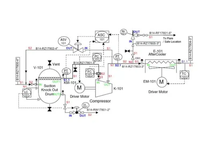
A complex and detailed section of a P&ID chart, highlighting various valve symbols.
What Exactly Is a P&ID, and How Is It Different from a Simple Drawing?
Confusing a P&ID with a basic process flow diagram (PFD)? This common mistake means you’re missing the critical details needed for real-world engineering and maintenance decisions. Knowing the difference is a must.
A P&ID (Piping & Instrumentation Diagram) is a detailed schematic showing all piping, equipment, valves, and instruments. Unlike a high-level PFD that just shows the process flow, a P&ID gives you the specific engineering details needed for design, operation, and maintenance.
A side-by-side comparison of a simple PFD and a detailed P&ID for the same process unit.
Understanding the Difference Between PFD and P&ID
Think of it like building a house. The PFD is the architect’s simple sketch showing where the kitchen, living room, and bathrooms are. The P&ID is the detailed construction blueprint that shows every electrical wire, plumbing pipe, and light switch. You can’t build a house from the sketch, and you can’t build a plant without a P&ID.
Hassan often tells his junior engineers, “The PFD tells you what we’re making. The P&ID tells you how we’re making it.”
The Definition and Key Differences
A P&ID is the single source of truth for a process unit. It’s a living document used from the initial design phase all the way through to decommissioning.
| Характеристика | Process Flow Diagram (PFD) | Piping & Instrumentation Diagram (P&ID) |
|---|---|---|
| Назначение | High-level process overview. | Detailed engineering reference. |
| Содержание | Major equipment, main process lines. | All equipment, all pipes, all instruments, all valves. |
| Details | No pipe sizes, insulation, or specific valve types. | Includes pipe classes, instrumentation loops, and specific P&ID valve symbols. |
| Audience | Management, Process Engineers. | Design, construction, and operations teams. |
Understanding this difference is crucial. When you need to know the exact type of valve to order or where an instrument is located for repair, you need the P&ID, not the PFD. The detailed P&ID valve symbols on this document tell you everything.
What Are the Key Parts of a P&ID That You Must Understand?
Feeling overwhelmed by all the lines and shapes on a P&ID? It’s easy to get lost if you don’t know the four main components. Focus on these core elements to start making sense of the chaos.
Every P&ID is built on four main components: process piping, equipment, instruments, and valves. Each is represented by its own set of symbols, including the crucial P&ID valve symbols, which together create a complete picture of the system.
How the Main Elements of a P&ID Work Together
A P&ID looks complex because it crams a huge amount of information into one drawing. But when you break it down into its main parts, it becomes much easier to read. Hassan taught me to scan a new P&ID in a specific order to build a mental map of the system.
1. Process Piping
These are the lines that connect everything. They represent the arteries and veins of the plant, transporting liquids, gases, and steam. The lines themselves contain information, indicating pipe size, material specifications, and flow direction (shown by an arrow).
2. Process Equipment
These are the major components where the process happens. They are represented by standardized shapes that are easy to recognize. Common examples include:
Pumps & Compressors: Move fluids through the pipes.
Heat Exchangers: Heat or cool the process fluid.
Tanks & Vessels: Store or react materials.
3. Process Instruments
These are the brains of the operation, providing measurement and control. They are shown as circles or bubbles containing letters that identify their function and measurement type (e.g., FT for Flow Transmitter, PT for Pressure Transmitter).
4. Valves in P&ID
This is where the direct control happens. Valves isolate equipment, control flow rates, and ensure process safety. Their importance cannot be overstated, which is why having standardized P&ID valve symbols is so critical for clear communication. Each symbol tells you exactly what that valve is designed to do. Without accurate P&ID valve symbols, the entire drawing would be useless for practical purposes.
Why Do the P&ID Valve Symbols Matter So Much?
Think a bowtie symbol is just a bowtie? In a P&ID, mistaking this simple symbol for another can mean installing the wrong type of valve, leading to leaks, poor control, or even a safety hazard.
Standardized P&ID valve symbols are a universal language for engineers. They ensure that a gate valve in Texas is understood as a gate valve in Dubai, preventing miscommunication during design, installation, and maintenance.
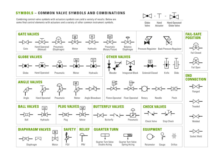
P&ID Valve Symbols as a Universal Engineering Language
Imagine trying to build a complex machine with instructions written in a language you don’t understand. That’s what a P&ID would be without clear, consistent symbols. These icons aren’t just pictures; they are precise instructions.
When my father’s factory gets an order for a project, the first thing we look at is the P&ID. The P&ID valve symbols tell us exactly what kind of valve the client needs, from its basic type to its method of actuation. A project’s success often hinges on correctly interpreting these symbols from the very beginning.
Typical Valve Symbols You Will See
While there are hundreds of variations, most P&ID valve symbols are based on a few common patterns. The base symbol for a standard 2-way valve is two triangles pointing toward each other on a process line. Small additions to this base symbol define the specific valve type.
| Тип клапана | Symbol Description |
|---|---|
| Задвижка | Base symbol with a vertical line drawn through the middle. |
| Шаровой клапан | Base symbol with an open circle in the middle. |
| Шаровой клапан | Base symbol with a filled-in (black) circle in the middle. |
| Заслонка | Base symbol with a circle and a line through it, representing the disc. |
| Обратный клапан | A modified base symbol with a line and a ‘Z’ or triangle indicating flow direction. |
| Регулирующий клапан | A globe valve symbol with an actuator (like a half-moon shape) on top. |
These P&ID valve symbols are the alphabet of process control. Learning them is the first step toward fluency in reading these essential engineering documents.
What are the Different Types of Valves Found on a P&ID?
Do you need to simply stop the flow, or do you need to finely control it? Using an on/off valve where you need a throttling valve is a classic mistake that can ruin your process control.
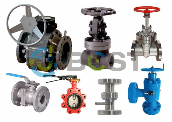
P&IDs feature a wide array of valves designed for specific jobs. These include isolation valves like gate and ball valves for on/off service, and control valves like globe and butterfly valves for throttling and regulation. The P&ID valve symbols clearly differentiate them.
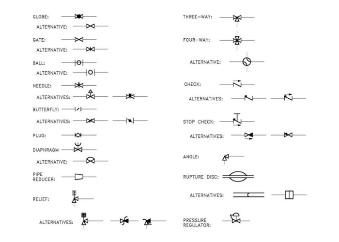
Choosing the Right Valve for Different Process Applications
Just as a carpenter has different saws for different cuts, an engineer uses different valves for different tasks. The P&ID uses a unique symbol for each one to ensure the correct “tool” is specified for the job.
Here are the most common types you’ll encounter and their primary roles:
- Задвижки: These are the workhorses for simple on/off isolation. Their design creates a clear, unobstructed path for flow when open, resulting in very little pressure drop. The vertical line in their P&ID valve symbols represents the gate.
- Шаровые краны: Known for their quick quarter-turn action, they provide a very tight seal when closed. They are excellent for on/off service but can also be used for some light throttling applications.
- Шаровые клапаны: These are the gold standard for flow regulation and throttling. Their internal design allows for precise control over the flow rate, but they also cause a significant pressure drop. The solid circle in their P&ID valve symbols highlights their flow-regulating purpose.
- Поворотные затворы: Common in large pipelines, these valves are lightweight, compact, and cost-effective. They are good for both on/off and throttling services, especially in water and air systems.
- Обратные клапаны: These are the one-way streets of a piping system. They automatically allow flow in one direction and prevent it from flowing backward (backflow), protecting equipment like pumps.
- Регулирующие клапаны: This is a broad category for any valve that is automatically adjusted by a control system. They are typically globe or butterfly valves equipped with an actuator (e.g., pneumatic, electric).
- Safety Relief Valves: These are non-negotiable safety devices. They automatically open to vent excess pressure if a system becomes over-pressurized, preventing catastrophic equipment failure. Their P&ID valve symbols are distinct and always draw attention during safety reviews.
Вопросы и ответы
What is the purpose of a P&ID diagram?
A P&ID is a detailed map of a process system, showing all piping, equipment, and instruments.
What valves are commonly shown in P&IDs?
You will commonly see gate, ball, globe, check, butterfly, control, and safety relief valves.
What is the difference between isolation valves and control valves?
Isolation valves are for simple on/off service (gate, ball), while control valves regulate flow (globe, butterfly).
Why are valve symbols important in engineering drawings?
They provide a clear, universal language that prevents mistakes in design, construction, and operation.
Заключение
A P&ID is the complete blueprint for a process system. Understanding the various types of valves and their corresponding P&ID valve symbols is essential for any professional working to ensure safe and efficient plant operations.


 English
 Arabic
 Russian
 French
 Spanish