
Feeling overwhelmed by the sheer number of industrial valves? Choosing the wrong one is a costly mistake that can hurt your system’s performance and safety. Let’s simplify this world together.
This guide will quickly teach you the 9 most common valve types. We will cover their core function and best use, from simple on/off ball valves to precise control valves, so you can select the right one for any job with confidence.
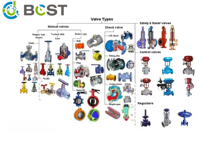
When is a Ball Valve Your Best Choice for Shutoff?
Tired of leaky valves causing problems in your process? You need a reliable, bubble-tight seal that you can count on every single time. The ball valve is your go-to solution for this.
A ball valve uses a rotating ball with a hole through it to provide a quick, quarter-turn shutoff. Its simple design offers excellent sealing performance, making it the perfect choice for on/off isolation applications in almost every industry you can think of.
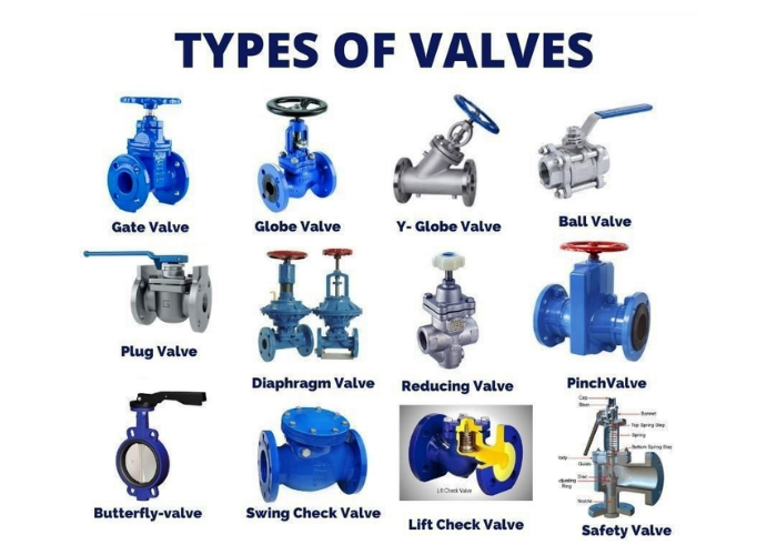
The ball valve is the undisputed king of on/off operation. The magic is in its simplicity. A 90-degree turn of the handle moves it from fully open to fully closed. This quick action is great for general isolation and emergency shutdowns. When open, the hole in the ball lines up with the pipe, creating a smooth path for the fluid. When closed, the solid side of the ball presses firmly against two soft seats, creating an incredibly tight seal. I’ve seen these valves hold back high pressure without losing a single drop.
There are a few key designs you should know about.
- Floating vs. Trunnion: In a standard floating ball valve, the ball is held in place by the seats and “floats” slightly. It’s perfect for most everyday applications. For high-pressure jobs or very large valves, a trunnion-mounted design is used. The ball is supported by a top and bottom stem (the trunnion), which holds it securely in place. This reduces the torque needed to turn the valve and improves sealing under high pressure. My father always said, “For the big jobs, the ball needs support.”
- Body Construction: A three-piece body is a maintenance favorite. You can swing the center section out to repair or replace the valve’s internal parts without having to cut the valve out of the pipeline. This saves a huge amount of time and money during plant shutdowns.
- Bore Type: A full-bore (or full-port) valve has a hole the same size as the pipe. This creates almost no pressure drop and is essential for lines that need to be cleaned with “pigs.” A reduced-bore valve has a slightly smaller opening. It’s more economical and is perfectly fine for most applications where a small pressure drop is acceptable.
| Feature | Description | Best For |
|---|---|---|
| Operation | Quarter-turn (90 degrees). | Fast on/off isolation. |
| Sealing | Excellent, bubble-tight shutoff. | Preventing leaks in critical lines. |
| Trunnion-Mounted | Ball is supported by a top and bottom stem. | High-pressure, large-diameter applications. |
| Three-Piece Body | Valve body can be taken apart for service. | Applications requiring frequent maintenance. |
Why Use a Gate Valve for Unrestricted Flow?
Is the pressure drop across your on/off valve killing your pump’s efficiency? You need a valve that gets completely out of the way when it’s open. The gate valve provides that perfect, straight-through path.
A gate valve uses a solid, sliding gate to block the flow. When fully open, the gate is lifted completely out of the fluid path. This provides a full, unobstructed port with very little pressure drop, making it perfect for pipeline isolation.
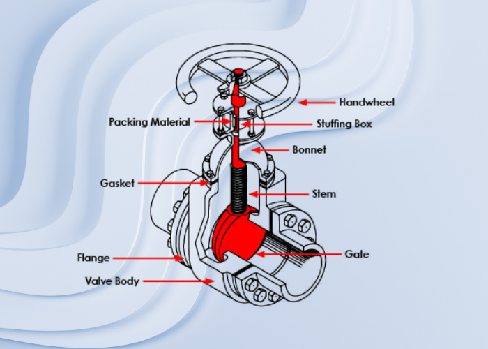
If a ball valve is a quick-action switch, a gate valve is like a slow, deliberate drawbridge. It uses a multi-turn handwheel to slowly lift a flat or wedge-shaped gate out of the fluid stream. The key benefit is what happens when it’s fully open: nothing. The fluid passes through as if the valve isn’t even there. This makes it the absolute best choice for applications where you need to minimize pressure loss over long pipelines, or for lines that require pigging.
However, there is one rule you must never, ever break with a standard gate valve: Do not use it for throttling. A gate valve is designed to be either fully open or fully closed. If you use it in a partially open position to try and control flow, the high-velocity fluid will slam against the bottom of the gate. This causes intense vibration and erosion that will quickly destroy the gate and the seats, causing the valve to fail and leak. I have seen valves completely ruined in a matter of months because someone used them to regulate flow.
You will also hear about two main stem designs:
- Rising Stem: On this type, the stem rises out of the handwheel as you open the valve. This provides a clear visual indication of whether the valve is open or closed. You can see it from across the room.
- Non-Rising Stem: The stem turns, but it does not rise. The gate moves up and down on threads inside the valve body. This design is more compact and is used in places with limited overhead space, like underground or in tight equipment rooms.
For really tough jobs with solids or slurries, like in a mining or wastewater plant, a special knife gate valve is used. It has a sharp a gate that can slice through thick media to create a seal.
Need to Precisely Control Your Flow?
Is your ball valve too sensitive, going from a trickle to a flood with a tiny movement? You’re trying to use an on/off switch for fine adjustment. You need a valve that is designed specifically for throttling and regulation.
A globe valve regulates flow by moving a disc against a seat in a winding, S-shaped path. This design gives you very precise throttling and flow control. The trade-off is that this path creates a higher pressure drop compared to a straight-through valve.
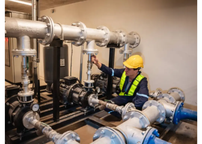
The globe valve is the original control valve. Unlike a gate or ball valve where the fluid has a straight shot, a globe valve forces the fluid to change direction multiple times. This winding, or “tortuous,” path is the secret to its excellent control. As you close the valve, the disc moves closer to the seat, and you can gradually and precisely “pinch” the flow. This is perfect for any application where you need to set and maintain a specific flow rate, such as a cooling water line, a fuel oil line, or a chemical dosing system.
This design comes at a cost: pressure drop. All that turning and changing direction saps energy from the fluid, which shows up as a pressure loss from the inlet to the outlet. This is a deliberate trade-off. You sacrifice some energy to gain a huge amount of control. An experienced engineer like Hassan knows this well. He would never specify a globe valve for simple isolation on a long pipeline, but he would absolutely insist on one for a critical process line that requires fine-tuning.
Globe valves are so good at control that they form the basis for most automated control valves. Even in its manual form, with a handwheel, it gives an operator the ability to carefully manage the process. When you need to turn things down just a little bit, this is the valve you should reach for. When specifying one, remember to check the arrow on the body—they are designed to have flow in a specific direction to ensure smooth operation and prevent damage.
How Do You Protect Your Pumps from Backflow?
Is reverse flow damaging your expensive pumps or contaminating your product? This costly and dangerous problem can be completely avoided with one simple, self-acting device. A check valve is your system’s one-way traffic cop.
A check valve, also known as a non-return valve, is a fully automatic device that allows fluid to flow in only one direction. It opens with forward flow and automatically slams shut to prevent any damaging backflow, protecting pumps, compressors, and other equipment.
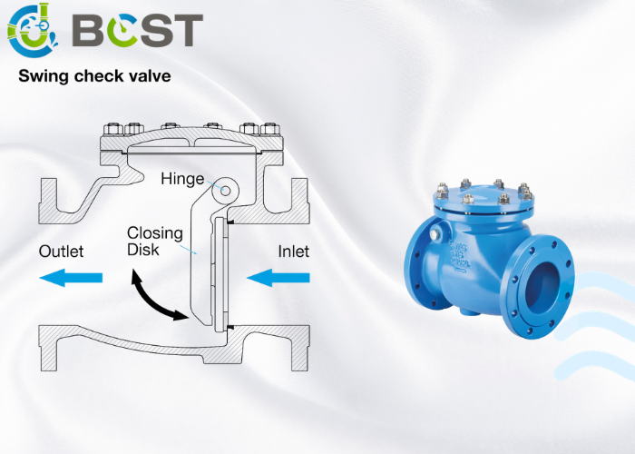
The beauty of a check valve is that it thinks for itself. It has no handle, no actuator, and no operator. It works purely on the energy of the flow. When the pump pushes fluid forward, the pressure opens the valve’s internal mechanism. If the pump stops or if pressure downstream becomes higher, the flow reverses, and that reverse pressure immediately pushes the mechanism closed, preventing flow from going backward. This is absolutely critical for protecting pumps. A spinning pump that is suddenly hit with reverse flow can be severely damaged.
The two most common types you will see are:
- Swing Check: This works like a simple flap or door hanging inside the valve. Forward flow pushes it open, and reverse flow pushes it closed. It’s simple, common, and provides a low-pressure drop.
- Lift Check: This type uses a piston or a ball that is lifted off its seat by forward flow. When flow stops, gravity and back pressure push the piston or ball back down onto the seat. These are great for high-pressure service and can be installed in vertical or horizontal lines.
One of the most important things I tell my clients is about proper installation. Every check valve has an arrow stamped or cast into the body. This arrow must point in the direction of normal system flow. I have been on service calls where an entire system wouldn’t work, only to find that a check valve was installed backward, completely blocking the flow from the pump. It’s a simple mistake with major consequences. Always double-check the arrow!
Looking for a Cost-Effective Valve for Large Pipes?
Are large diameter ball or gate valves breaking your project budget? You need a solution that is compact, lightweight, and more affordable for those big pipeline jobs. The butterfly valve is your answer.
A butterfly valve controls flow with a large disc that rotates in the flow path. Its simple, quarter-turn design is lightweight, compact, and much more affordable than a ball or gate valve, especially as you get into large pipe sizes (above 12 inches).
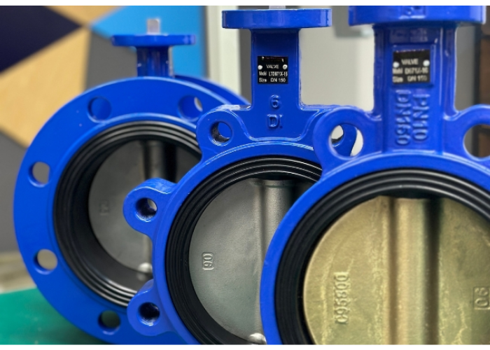
The butterfly valve is a master of large-scale applications. Instead of a heavy body and a large ball or gate, it has a relatively thin body and a simple disc that pivots on a central stem. This makes it significantly lighter and more compact. For a 24-inch pipeline, the weight and cost savings compared to a ball valve are enormous. Like a ball valve, it operates with a quick quarter-turn, making it easy to automate.
There are a few main types, and the differences are all about sealing performance:
- Centric (or Resilient Seated): This is the basic design where the stem is centered in the disc, and the disc seals against a soft, rubber-like seat. It’s perfect for low-pressure applications like water treatment, HVAC, and food processing.
- Double and Triple Offset: For more demanding jobs with high pressure, high temperature, or chemicals, you need an offset butterfly valve. These designs move the disc and stem to create a “camming” action. A triple offset valve uses a metal seat and a laminated disc seal. As it closes, the seal only contacts the seat in the final moment, which eliminates friction and wear. My father’s factory started producing triple offset valves years ago, and they are incredible. They can provide a true zero-leakage seal that rivals a ball valve, even in very harsh services.
Compared to a ball valve, a butterfly valve’s disc is always in the flow path, so it does create a small amount of pressure drop even when fully open. But for many large-diameter applications, this is a very small price to pay for the huge benefits in cost, weight, and space savings.
Why Is a Plug Valve the King of Zero-Leakage?
Are even your best ball valves showing tiny leaks in tough, corrosive, or dirty services? Some jobs demand absolute, undeniable, bubble-tight shutoff. For these, you need the superior sealing power of a plug valve.
A plug valve uses a tapered or cylindrical plug that rotates to block the flow. This design provides a very large metal-to-metal sealing area, making it an excellent choice for achieving zero leakage, especially in challenging services with corrosive media or solids.
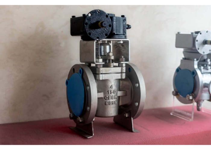
While a ball valve seals on two relatively small rings (the seats), a plug valve seals over a wide surface area. This robust sealing makes it a favorite in industries like petrochemicals and natural gas distribution, where leaks are not an option.
There are two main families of plug valves:
- Lubricated: This classic design has grooves in the plug surface that are injected with a special sealant. This sealant does two jobs: it lubricates the valve to make it easier to turn, and it fills any tiny imperfections to create a perfect, bubble-tight seal. Even if the metal surfaces get a little scratched from dirty service, the sealant ensures the valve won’t leak. They are incredibly reliable for isolating natural gas lines.
- Non-Lubricated: These valves have a soft sleeve or liner made of a polymer material like PTFE that is fitted into the valve body. The plug rotates within this sleeve, which provides the seal and reduces friction. These are great for highly corrosive chemical applications where you want to avoid any contamination from a lubricant.
The main drawback of plug valves is that they typically require more force (torque) to operate than a ball valve of the same size. But in return for that extra effort, you get an extremely rugged and dependable valve that can handle difficult fluids. When a client tells me they have a slurry or a chemical that just keeps ruining their ball valves, a plug valve is often the solution I recommend.
What’s the Difference Between a Safety and a Relief Valve?
Are you worried about a boiler or pressure vessel exploding? You need a completely automatic and reliable device to vent excess pressure during an emergency. Safety and relief valves are your system’s critical last line of defense.
A safety valve rapidly “pops” fully open at its set pressure for maximum discharge, and is primarily used for gases and steam. A relief valve opens gradually and proportionally to the overpressure, and is typically used for liquids. Both are designed to automatically protect your system.
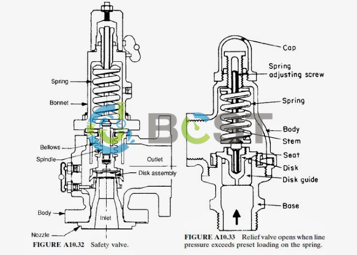
These valves are purely for protection. As I mentioned before, they are the most important valve in the plant on the one day they are needed. They are not used for process control; they are there to prevent a catastrophic failure.
The key difference is their action:
- Safety Valve (Pop Action): When a safety valve on a steam boiler reaches its set pressure, it doesn’t just open a little. It instantly pops to its full lift position. This is a deliberate and very fast action designed to dump a massive volume of steam or gas in a huge hurry to prevent the system pressure from climbing any higher. This rapid opening is a requirement by safety codes like ASME for compressible fluids (gases/steam) where pressure can build up explosively.
- Relief Valve (Proportional Action): A relief valve is more civilized. When the pressure in a liquid-filled pipe a little, the relief valve opens just a tiny bit to bleed off that excess pressure. If the pressure builds more, it opens more. Its opening is proportional to the overpressure. This is ideal for liquid service, for example, to handle the thermal expansion of water in a line that is sitting in the hot sun. It keeps the pressure from rising without a dramatic, full-volume discharge.
| Type | Action | Primary Service | Main Purpose |
|---|---|---|---|
| Safety Valve | Pops fully open at set pressure. | Gas, Steam (Compressible fluids) | Emergency rapid pressure discharge. |
| Relief Valve | Opens proportionally to overpressure. | Liquids (Incompressible fluids) | Gradual pressure control. |
How Does a Control Valve Automate Your Entire Process?
Is manually adjusting handwheels all day slow, inefficient, and inaccurate? Your modern process requires constant, precise, and automatic adjustments to maintain quality and safety. The control valve is the hands and feet of your automated system.
A control valve automatically adjusts its position to regulate flow, pressure, level, or temperature. It combines a valve body with an actuator that takes a signal from a process controller (like a PLC or DCS), acting as the final physical element in an automated control loop.
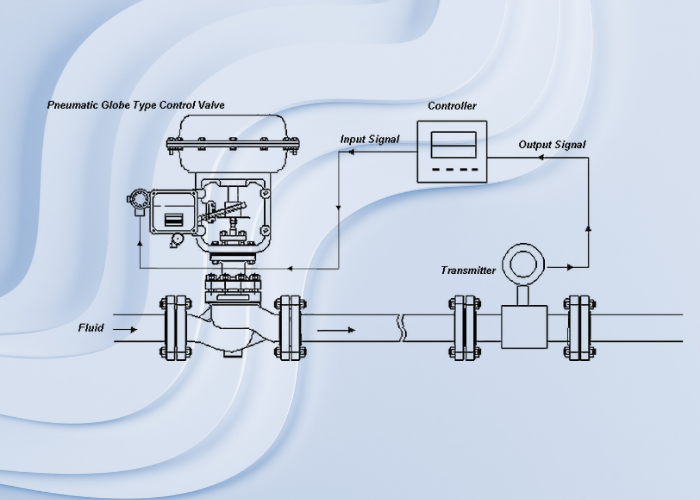
A control valve is much more than just a valve; it’s a sophisticated piece of machinery. It consists of three main parts working in concert:
- Valve Body: This is the part that handles the fluid. Very often, a globe-style body is used because of its excellent throttling characteristics, which we discussed earlier.
- Actuator: This is the “muscle” that physically moves the valve. The most common type is a pneumatic actuator that uses compressed air pushing on a diaphragm or piston. You will also see electric actuators that use a motor and gears.
- Positioner: This is the “brain” of the valve. It receives the control signal (e.g., a 4-20 mA electronic signal) from the main process controller. It then compares that signal to the valve’s actual position and adds or vents air to the actuator to move the valve to the exact position required.
Imagine a simple control loop to heat a tank. A temperature sensor tells the main controller the water is too cold. The controller sends a signal to the control valve on the steam line. The positioner on the valve interprets this signal and tells the actuator to open the valve a little more, letting in more steam. As the water warms up, the sensor reports this, and the controller tells the valve to close slightly. This happens continuously, 24/7, keeping the temperature perfectly stable. An entire chemical plant designed by an engineer like Hassan is run by hundreds or thousands of these loops working together.
How Can You Regulate Pressure Without Any External Power?
Is running electrical or air lines to a remote valve for simple pressure control too expensive and complicated? You need a simple, standalone, and reliable pressure control device that can work anywhere. A self-operated regulator is the perfect solution.
A self-operated regulator automatically maintains a desired downstream pressure without needing any external electricity or compressed air. It cleverly uses the fluid’s own energy, balanced against a spring and diaphragm, to control itself, making it a simple, reliable, and energy-saving solution.
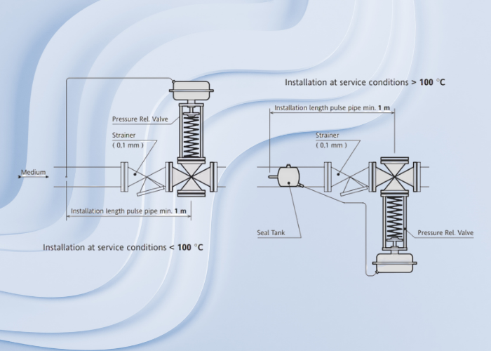
The working principle of a regulator is pure mechanical genius. Let’s take the most common type, a pressure reducing regulator:
- High-pressure fluid enters the inlet.
- The fluid flows past the valve plug and into the outlet pipe.
- A small sensing line feeds some of this lower downstream pressure to the underside of a flexible diaphragm.
- A large, adjustable spring on top of the diaphragm pushes down.
It’s a constant balancing act. If the downstream pressure gets too high, it pushes the diaphragm up, which lifts the valve plug and starts to close the valve, reducing the flow. If the downstream pressure gets too low, the spring force wins, pushing the diaphragm down and opening the valve more to increase the pressure. It’s a complete, self-contained control loop in one mechanical device. They are incredibly reliable because there are no electronics to fail. I recommend them all the time for applications like utility steam lines or instrument air headers where you just need to step down the pressure from a high-pressure source and keep it steady. They save energy, are easy to install, and just keep on working.
Conclusion
Valves can be simplified into three jobs: isolation, control, and protection. By understanding a valve’s core job, you can choose the right one, ensuring your system runs safely and efficiently.


 English
 Arabic
 Russian
 French
 Spanish