
Choosing the wrong valve size can starve your system or cause damaging instability. It’s a common mistake that wastes energy and money, undermining your whole process design.
To select the correct pneumatic valve size, you must first calculate the required Flow Coefficient (Cv) based on your system’s flow rate, fluid properties, and pressure conditions. This Cv value is then used to choose a valve that can provide stable control without being oversized or undersized.

I remember a project with Hassan, a chief engineer at a chemical plant. They were having trouble with a new production line; the output was inconsistent, and a key control loop was unstable. The original supplier had simply matched the valve size to the pipe size, a 4-inch valve for a 4-inch pipe. But after Hassan and I ran the calculations, we found the required Cv was much lower than what a 4-inch valve provided. The valve was oversized, constantly opening and closing just a tiny fraction to meet the flow demand, which created the instability. We replaced it with a properly sized 2.5-inch valve. The system immediately stabilized, and product quality became consistent. This taught me a powerful lesson: in valve sizing, the process requirements, not the pipe size, must always be the guide.
What is the Flow Coefficient (Cv) and Why Does It Matter Most?
You see a Cv value on a valve’s datasheet, but what does it really mean for your system? Ignoring this number can lead to poor performance, even if the valve fits the pipe perfectly.
The Flow Coefficient, or Cv, is a standardized measure of a valve’s efficiency in allowing fluid to pass through it. It represents the volume of water (in US gallons per minute) that will flow through a fully open valve with a one psi pressure drop.

The Cv is the single most important factor in valve sizing because it connects your process needs directly to a valve’s physical capability. Think of it as the true measure of a valve’s capacity. A larger Cv means the valve can pass more fluid with less restriction. The goal is not to pick the biggest Cv, but the right one. The selection process always starts with your system’s parameters. You must know your required flow rate, the pressure of the fluid entering the valve (P1), the pressure you need downstream (P2), and the fluid’s specific gravity. You plug these values into a specific Cv formula. The result of that calculation is the Cv your system requires. You then select a valve from a manufacturer’s chart that has a Cv rating matching your calculated need, typically when the valve is between 60% and 80% open for control applications. This ensures the valve operates in its most stable and efficient range.
| Parameter | What It Is | Why It’s Important for Cv |
|---|---|---|
| Flow Rate (Q) | The volume of fluid you need to move per unit of time (e.g., GPM, m³/hr). | This is the primary performance target. All calculations are based on achieving this flow. |
| Inlet Pressure (P1) | The pressure of the fluid just before it enters the valve. | A higher inlet pressure will force more fluid through the valve for a given opening. |
| Outlet Pressure (P2) | The pressure of the fluid just after it leaves the valve. | The difference between P1 and P2 (Pressure Drop) is the driving force for the flow. |
| Specific Gravity (SG) | The density of the fluid relative to water. | Denser fluids (higher SG) are harder to move and require a larger Cv for the same flow rate. |
How Do Different Fluids Affect Valve Sizing?
You wouldn’t use the same hose to pump air, water, and honey. Similarly, your valve choice must change based on whether you are controlling a gas, a liquid, or a thick slurry.
The fluid’s state (liquid or gas) and properties like viscosity determine which sizing formula to use. Gases are compressible and can experience choked flow, requiring special calculations, while viscous liquids create more friction and demand a larger valve.
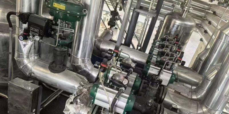
Sizing a valve is not a one-size-fits-all process. The fluid itself dictates the rules. For liquids like water or thin chemicals, the standard Cv calculation is straightforward. But if you are working with a thick, viscous fluid like heavy oil or a slurry, you need to apply a viscosity correction factor. The extra friction from the thick fluid reduces the valve’s effective capacity, so you’ll need to select a larger valve to achieve the same flow rate. Gases are even more complex. Because gases are compressible, their density changes as they pass through the valve and the pressure drops. This means you have to use a different set of Cv formulas that account for this compressibility. Furthermore, with gases, you can reach a condition called “choked flow” or “critical flow.” This happens when the outlet pressure drops to a certain point (usually around half the inlet pressure). At this point, increasing the pressure drop further will not increase the flow rate. Sizing a valve for gas requires you to check for choked flow to ensure your selection is accurate and predictable.
Why is Sizing the Actuator as Important as the Valve?
You have selected the perfect valve body, but it’s sluggish or won’t close fully. The problem may not be the valve at all, but an undersized actuator struggling to power it.
The actuator provides the force (torque) to open and close the valve against process pressures. An undersized actuator will fail to operate the valve reliably, while an oversized one is wasteful and can damage the valve stem.

I often see engineers spend all their time on the valve’s Cv calculation and then treat the actuator as an afterthought. This is a critical mistake. The actuator is the engine that drives the valve. To size it correctly, you first need to know the torque requirement of the valve. This “break torque” is the force needed to get the valve moving from a fully closed or open position. This value changes based on the valve type (ball valves require more torque than butterfly valves) and the pressure difference across the valve. A higher pressure drop means the actuator has to work harder. Next, you must consider your plant’s available air supply pressure. This is the “power” you have to run the actuator. You then consult an actuator sizing chart, which shows you which model can produce the required torque using your available air pressure. It’s always wise to add a safety factor of around 25-50% to ensure the actuator can handle unexpected conditions or wear over time. Choosing the right actuator ensures the valve you so carefully sized will actually perform as intended in the real world.
Conclusion
Sizing a pneumatic valve is a precise process, not a guess. By calculating the required Cv and carefully considering the fluid and actuator, you ensure your system operates safely, efficiently, and reliably.


 English
 Arabic
 Russian
 French
 Spanish