
How Does a Gas Solenoid Valve Work? An Industrial Guide to Operation and Testing
Quick Answer: Understanding Gas Solenoid Valves
- A gas solenoid valve controls gas flow electromagnetically, acting as a crucial safety component in fuel systems.
- It operates by energizing a coil, creating a magnetic field that moves a plunger to open or close the valve.
- Testing involves safety protocols, a multimeter for coil integrity, and observation for proper mechanical action.
- Selection criteria for industrial use include pressure, flow (Cv), media compatibility, and critical hazardous location ratings.
The gas solenoid valve is often considered the “heart” of fuel system safety and control. Its precise operation dictates when and how gas flows, making it an indispensable component for industrial processes reliant on combustible fuels. For fuel industry owners, understanding the intricate mechanics of how a gas solenoid valve works, how to properly test it, and how to troubleshoot common issues is not just good practice—it’s essential for maintaining safety, ensuring compliance, and maximizing uptime. This guide offers a deep dive into the mechanics, types, and troubleshooting steps specific to industrial applications. While this article focuses on gas systems, you might find our insights on PVC Valves for Non-Corrosive Environments useful for contrasting material compatibility in other fluid handling contexts.
What is an Industrial Gas Solenoid Valve?
An industrial gas solenoid valve is an electromechanically operated valve that controls the flow of gases in a system. It serves as a critical safety and control device, allowing for rapid and precise opening or closing of a gas line in response to an electrical signal. Unlike manual valves, solenoid valves can be integrated into automated control systems, making them ideal for complex industrial processes where remote or automatic operation is required.
The Core Function: Controlling Gas Flow
At its core, a gas solenoid valve’s function is simple: to start, stop, or sometimes divert the flow of combustible gases, such as natural gas, propane, or other process gases, using an electromagnetic force. This allows for safe system startup, controlled operation, and immediate shutdown in emergency situations, preventing uncontrolled gas releases or over-pressurization.
Key Components of a Gas Solenoid Valve
Understanding the internal structure is crucial to understanding how a gas solenoid valve works:
- The Coil: An electromagnetic coil made of many turns of wire. When energized with an electric current, it generates a magnetic field.
- The Plunger (Armature): A ferromagnetic cylinder or disc located within the coil. It is the movable part directly acted upon by the magnetic field.
- The Seal: An elastomer or metallic disc attached to the plunger, designed to create a leak-tight seal against the valve seat.
- The Valve Body: The main housing of the valve, containing the inlet, outlet, and the valve seat (the opening the seal closes against).
- The Spring: Typically a return spring, used to hold the plunger in its default (normally closed or normally open) position when the coil is de-energized.

How Does a Gas Solenoid Valve Work? (The Sequence of Operation)
The operation of a gas solenoid valve follows a clear sequence, converting electrical energy into mechanical movement to control gas flow.
The Electromagnetic Principle
When an electrical current is supplied to the solenoid coil, it instantly generates a powerful magnetic field. This magnetic field is focused around the plunger, which is a ferrous material. The magnetic force pulls the plunger either into or out of the coil’s core.
The Opening and Closing Process
- Normally Closed (NC) Valve (Most Common for Safety): In its default, de-energized state, a spring holds the plunger down, ensuring the seal is tightly pressed against the valve seat, preventing gas flow. When the coil is energized, the magnetic field overcomes the spring force, pulling the plunger upwards. This lifts the seal off the seat, allowing gas to flow through the valve. When power is removed, the magnetic field collapses, and the spring pushes the plunger back down, closing the valve.
- Normally Open (NO) Valve: The opposite is true for Normally Open valves. The valve is open when de-energized and closes when the coil is energized.
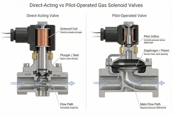
Direct Acting vs. Pilot Operated: Which One is Right for High-Pressure Fuel Systems?
There are two primary types of gas solenoid valves, distinguished by how the plunger mechanism controls the main flow path:
- Direct Acting: In a direct-acting valve, the solenoid coil directly lifts the main plunger to open or close the primary orifice. These valves are relatively simple, fast-acting, and can operate from zero or very low differential pressures. They are typically used for smaller line sizes and lower flow rates. Their reliability at zero differential pressure makes them a good choice for critical shut-off applications where consistent pressure cannot be guaranteed.
- Pilot Operated (Indirect Acting): Pilot-operated valves use a smaller “pilot” solenoid to control a small flow of pressure from the main line, which then acts on a larger diaphragm or piston to open or close the main valve. This design harnesses the system’s own differential pressure to assist in actuation, allowing these valves to control much larger flow rates and higher pressures with a relatively small coil. However, they typically require a minimum differential pressure (e.g., 5-10 psi) to operate effectively. For high-pressure fuel systems, pilot-operated valves are often preferred for their ability to handle large volumes, provided the minimum differential pressure requirement is met.
How to Test a Gas Valve Solenoid: A Step-by-Step Guide
When troubleshooting a fuel system, testing the gas valve solenoid is a crucial step. Always prioritize safety during this process.
Step 1: Safety First – Protocols for Isolating Gas Lines
Before performing any diagnostic or maintenance work on a gas solenoid valve, ensure the gas supply to the valve is completely shut off and locked out. Electrically isolate the coil by turning off the power to the control circuit. Confirm both gas and electrical isolation using appropriate safety procedures and equipment. Failure to do so can result in serious injury, fire, or explosion. Allow the coil to cool down if it has been recently energized.
Step 2: The Multimeter Test – Checking for Continuity and Resistance
This test checks the integrity of the solenoid coil.
- Remove power to the valve coil.
- Disconnect the electrical leads from the solenoid coil terminals.
- Set your multimeter to the Ohms (Ω) setting for resistance.
- Place the multimeter probes onto the two coil terminals.
- A healthy coil should show a resistance reading within the manufacturer’s specifications (e.g., 50-500 ohms, widely variable by manufacturer and voltage).
- If the multimeter displays “OL” (Open Loop) or infinite resistance, the coil is “open”—meaning a wire is broken, and the coil is faulty.
- If the reading is very low (close to 0 ohms), the coil may have a “short,” indicating a fault.

Step 3: Auditory and Visual Checks – Identifying the “Click” of the Plunger
This test is performed with caution after verifying proper power connection and gas isolation.
- Briefly apply the correct voltage to the solenoid coil (ensure gas path remains closed during this test, or bypass if safe to do so).
- Listen closely for a distinct, sharp “click” as the coil energizes and the plunger moves. A weak or absent click often indicates a problem with the coil, plunger, or internal mechanism.
- If possible and safe, sometimes you can gently feel for vibration or movement of the plunger component when energized, confirming mechanical action.
If the multimeter test shows a good coil but there’s no solid click, the plunger might be mechanically stuck due to dirt, corrosion, or a broken spring.
Common Gas Solenoid Valve Failure Symptoms
Identifying the symptoms of a malfunctioning gas solenoid valve quickly can prevent extended downtime and potential safety hazards. Here are typical indicators:
The Valve Won’t Open
This is a common symptom, often leading to a system trip or lockout. Causes include:
- Coil Burnout: The most frequent cause. A multimeter test will reveal an open circuit or incorrect resistance.
- Low Voltage: Insufficient voltage reaching the coil means it can’t generate enough magnetic force to move the plunger.
- Stuck Plunger: Debris, corrosion, or a swelling seal can mechanically prevent the plunger from moving, even if the coil is good.
The Valve Won’t Close (Internal Leaking)
A valve that fails to close completely can lead to continuous flow, posing significant safety and control issues. Causes include:
- Debris in the Seal Area: Small particles (rust, dust) lodged between the seal and the seat prevent a tight closure.
- Worn-Out Springs: A weak or broken return spring may not have enough force to push the plunger back to the closed position.
- Damaged or Swollen Seals: Chemical incompatibility
or aging can cause the seal material to degrade, crack, or swell, preventing an effective seal.
Humming or Buzzing Noises
While a slight hum can be normal for AC-powered coils, excessive or rhythmic buzzing often indicates an issue:
- AC Voltage Issues: Fluctuations or incorrect voltage can cause the coil to vibrate more than usual.
- Mechanical Vibration: A loose or misaligned shading coil (in AC valves) or mechanical wear causing plunger misalignment can create excessive noise.
Industrial Selection Criteria for the Fuel Industry
Selecting the correct gas solenoid valve for fuel systems involves more than just understanding how a gas solenoid valve works. It requires a meticulous evaluation of application-specific needs to ensure long-term reliability and safety.
Pressure and Flow Requirements (Cv)
Proper sizing is paramount. The valve’s pressure rating must safely exceed peak system pressures, and its flow coefficient (Cv) must be correctly matched to the required flow rate for your industrial burners or processes. Oversizing can lead to poor control and increased wear, while undersizing will restrict flow and efficiency. Understanding the differential pressure requirements for pilot-operated valves is also critical. For insights into selecting appropriate materials for various applications, remember that using materials like PVC for compressed air safety highlights why material selection must match the media and pressure conditions perfectly.
Hazardous Location Ratings: Understanding Explosion-Proof Requirements
In the fuel industry, the presence of flammable gases necessitates specialized hazardous area certifications. Gas solenoid valves for these environments must be designed and certified as explosion-proof. Key certifications include ATEX (for Europe), UL (Underwriters Laboratories), and FM (Factory Mutual) approval. These ratings ensure the valve’s electrical components can operate safely without igniting surrounding explosive atmospheres. Always ensure the chosen valve’s rating matches or exceeds the classification of your operating environment.
Frequently Asked Questions About Gas Solenoid Valves
Q: Why is my gas solenoid valve getting hot?
A certain amount of heat is normal, especially for continuously energized AC coils, which can feel quite warm to the touch. However, excessive heat beyond what’s specified by the manufacturer can indicate a problem. This might be due to incorrect voltage, operating outside its specified temperature range, or a short circuit within the coil, leading to premature coil failure. If unsure, measure the coil temperature and compare it to manufacturer specifications.
Q: Can I replace just the solenoid coil?
In many cases, yes. The solenoid coil is often a replaceable component on industrial gas valves, allowing for maintenance cost savings compared to replacing the entire valve body. Ensure that the replacement coil matches the original’s voltage, wattage, and hazardous area rating. Always follow manufacturer instructions for coil replacement.
Q: How long do industrial gas valves typically last?
The lifespan of an industrial gas solenoid valve depends heavily on its quality, operating conditions (pressure, temperature, media cleanliness), and cycle frequency. High-quality industrial valves are designed for millions of cycles and can last many years with proper maintenance. Valves in harsh environments or with very high cycle rates will have a shorter lifespan. Regular inspection and testing are key to predicting and preventing unexpected failures.
Q: What is the difference between a gas solenoid and a gas regulator?
A gas solenoid valve is an on/off device that either permits or stops gas flow in response to an electrical signal. It has no ability to modulate pressure. A gas regulator, conversely, is a mechanical device designed to reduce and maintain a constant output pressure regardless of fluctuations in the input pressure or output flow rate. They serve distinct but often complementary roles in a fuel system: the solenoid valve for safety and control, and the regulator for pressure management.
Conclusión
Understanding how a gas solenoid valve works, from its fundamental electromagnetic principles to its operational nuances and failure symptoms, is vital for safe and efficient fuel system management. Regular testing and a meticulous approach to selection considering parameters like media compatibility, pressure, flow coefficients, and crucial hazardous area certifications are non-negotiable for industrial owners. These precision components are integral to safety protocols and operational reliability. At BCST Valve, we are committed to providing robust and compliant solutions for the most demanding fuel industry applications.
Need technical specifications or custom instrumentation solutions?


 English
 Arabic
 Russian
 French
 Spanish