
Struggling to read complex P&IDs? Misreading a single symbol can risk system failure. But understanding these diagrams is your first step to ensuring safety and efficiency in any project.
A check valve symbol is a graphic used on engineering drawings to show a non-return valve. The basic symbol is a triangle pointing in the direction of flow, with a vertical line at its base. This indicates the valve only allows fluid to move one way.
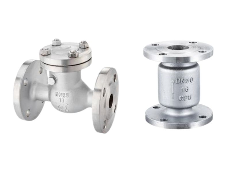
From a young age, I watched my father build his valve business. He taught me that precision is everything. That precision begins with a shared language, and in our industry, that language is the symbols on engineering diagrams. A small triangle on a page can prevent a million-dollar disaster. An engineer I work with, Hassan, manages entire refinery designs. For him, correctly reading a check valve symbol is a daily, critical task that protects lives and investments. Let’s break down this language together so you can read any diagram with confidence.
The Basic Symbol Structure and What It Means
Are you confused by the simple shapes on a diagram? The triangle and line of a check valve symbol seem basic, but they hold critical information for your system’s successful operation.
The basic check valve symbol consists of a triangle and a vertical line. The triangle points in the allowed direction of flow, while the vertical line at its base represents the seal that prevents backflow.

The beauty of this symbol is its simplicity. It’s a universal language for engineers and technicians worldwide. To understand it fully, you just need to know what each part represents. Think of it as a one-way street sign for fluids in your pipes. When you see this symbol, you immediately know the primary function of the valve without needing extra notes. It’s an efficient way to communicate a vital function on a crowded diagram.
Understanding the Components
Each element of the symbol provides essential information at a glance. Let’s break them down:
- The Triangle: This is the core of the symbol. Its most important feature is the point, which always indicates the direction of allowed fluid flow. If the triangle points right, the fluid is meant to travel to the right.
- The Vertical Line: This line sits at the wide, flat base of the triangle. It represents the valve’s seat or seal. This is the barrier that stops fluid when it tries to flow backward.
These two parts combine to clearly show a one-way gate.
| Componente | Visual Representation | Meaning |
|---|---|---|
| Triangle | A filled or unfilled triangle | Acts as an arrow, showing the path of forward flow. |
| Line | A vertical line at the triangle’s base | Represents the seal that blocks any reverse flow. |
Mastering this basic structure is the first step toward reading any piping and instrumentation diagram (P&ID) like a professional.
Reading the Check Valve Symbol in Context
Placing a valve is easy, but placing it right is hard. Misinterpreting a symbol’s position on a P&ID can lead to equipment damage or complete process failure. Let’s fix that.
To read the symbol correctly, first find the flow direction from the triangle’s point. Then, check its location. It’s usually placed on the discharge side of pumps to protect them from damaging backflow.
A P&ID is a map of your process. The position of a check valve symbol on this map is just as important as the symbol itself. One of its most critical roles is protecting expensive rotating equipment like pumps and compressors. These machines are designed to push fluid forward. If the system shuts down and that fluid rushes backward, it can spin the pump’s impeller in reverse. This “backspin” can destroy motors, bearings, and seals in seconds.
By placing a válvula antirretorno directly after the pump’s outlet, you create a barrier. The moment the pump stops, the check valve closes, preventing any backflow and saving the equipment. Hassan, the Chief Engineer, tells me that this is one of the first things his team checks during a design review. A missing or misplaced check valve on a pump discharge line is a major red flag that must be corrected immediately. It’s a simple rule that prevents very expensive problems.
Decoding Standard Symbols: ISO, ASME, and DIN
Working on an international project? Different standards like ISO, ASME, and DIN can use slightly different symbols, leading to confusion and errors if you are not careful.
While the core concept is the same, standards like ISO 10628 and ASME (P&ID) might have slight variations. For example, some might use an unfilled triangle, while others use a filled one.
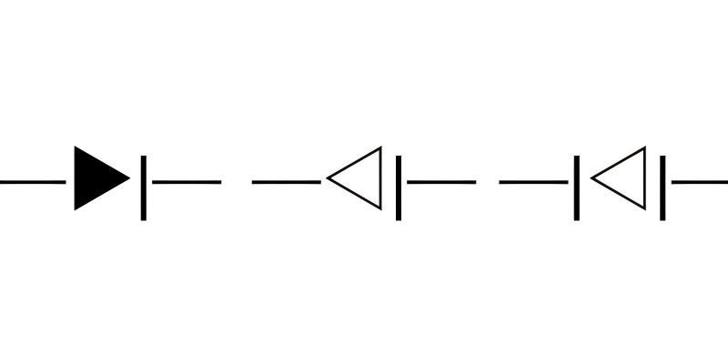
Engineering is a global field, and different regions have developed their own standards over time. While they all aim for clarity, the symbols can vary. This is especially true for a common component like a check valve. The good news is that the core logic—a triangle for flow and a line for the stop—is almost always present. However, the exact appearance can change.
For any project, the most important document is the diagram’s legend or key. This section defines every symbol used in that specific set of drawings. Before you start interpreting any P&ID, always look at the legend first. It’s the official dictionary for that project.
| Standard | Common Symbol Style | Notes |
|---|---|---|
| ASME | Unfilled triangle with a vertical line. | The most widely recognized style in North America. |
| ISO 10628 | Often similar to ASME, can be filled or unfilled. | Aims to create a universal standard for chemical plants. |
| DIN 2481 | May use a different shape or orientation. | The German standard can have unique representations. |
Always refer to the project’s P&ID legend to confirm the exact check valve symbol being used.
Matching the Symbol to the Check Valve Type
Think all check valves are the same? Using a generic symbol can hide important details, leading you to specify a swing valve where a spring-loaded one is needed.
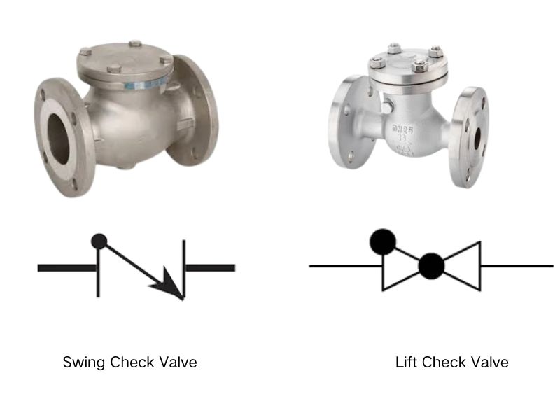
The basic check valve symbol can be modified to show the internal mechanism. An arc can indicate a swing check, a ball shows a ball check, and a zig-zag line means it is spring-loaded.
A P&ID is not just about showing that a check valve exists; it’s about communicating what kind of check valve is needed. The specific design of a check valve determines how it performs. A simple swing check valve is great for horizontal water lines but would perform poorly in a vertical line with upward flow. I remember a young engineer who specified a standard swing check for a vertical pipe on a pump discharge line. During the design review, I pointed out that gravity might not be enough to close the valve properly. We changed the specification to a spring-loaded check valve. The symbol on the P&ID was updated to include the zig-zag for the spring. This small change, reflected in the symbol, ensured the system would work safely and reliably.
| Symbol Variation | Represents | Best Use Case |
|---|---|---|
| Symbol + Arc | Swing Check Valve | Horizontal lines with low-velocity fluids. |
| Symbol + Ball | Ball Check Valve | Viscous fluids or systems where a quick seal is needed. |
| Symbol + Zig-Zag | Spring-Loaded Valve | Any orientation (vertical, horizontal), prevents water hammer. |
| Symbol + T-Shape | Lift Check Valve | High-pressure gas or steam lines, usually vertical flow. |
Symbol Differences Between P&ID and PFD
Ever looked at a PFD and a P&ID for the same process and noticed differences? Understanding why the symbols change is key to grasping the purpose of each diagram.
A Process Flow Diagram (PFD) shows the main process. A P&ID is more detailed. The check valve symbol on a PFD might be simple, while on a P&ID it will be specific and include tag numbers.
Think of it like maps. A Process Flow Diagram (PFD) is like a world map. It shows you the main continents (major equipment) and the oceans between them (major process flows). Its purpose is to give a high-level overview of how the plant works. On a PFD, you might see a simplified, generic check valve symbol only if it’s critical to understanding the main process. Many minor check valves won’t be shown at all.
A Piping and Instrumentation Diagram (P&ID), on the other hand, is like a detailed street map of a city. It shows every single street (pipe), traffic light (instrument), and building (equipment). On a P&ID, every check valve must be shown with a precise symbol that often indicates its type (swing, ball, etc.). It will also have a unique tag number, size, and material specification attached to it. Hassan and his team use PFDs for initial planning and P&IDs for detailed engineering, procurement, and construction.
How to Choose the Correct Symbol for Your Project
Creating a new diagram and unsure which symbol to use? Choosing the wrong one can mislead colleagues and cause costly mistakes during procurement or construction.
To choose the right symbol, first determine the valve’s function. Then, select the symbol variation that best represents that type (e.g., basic, spring-loaded). Always follow your project’s established symbol legend.
If you are the one creating the diagram, you have the responsibility to be clear and accurate. Choosing the correct symbol is a critical step that impacts everyone who uses your drawing, from the project manager to the installation technician. Here’s a simple process to follow:
- Define the Function: First, ask what this check valve needs to do. Is it just preventing backflow in a horizontal pipe? Does it need to work vertically? Does it need to open at a specific pressure (this is called cracking pressure)?
- Select the Valve Type: Your answer to the first question will determine the type of check valve needed. A vertical line needing fast closure points to a spring-loaded check valve. A simple horizontal water line might only need a swing check.
- Consult the Legend: Your project or company should have a standard P&ID symbol legend. Find the approved symbol for the valve type you selected. Using the standard symbol ensures consistency across all project drawings.
- Draw and Annotate: Place the correct symbol on the diagram in the right location and orientation. Then, add the necessary annotations, such as the tag number, line number, size, and material class. This complete information makes your drawing clear, professional, and easy to execute.
Frequently Asked Questions (FAQ)
Q1: What is the most common mistake when reading a check valve symbol?
A: The most common mistake is misinterpreting the flow direction. Always remember that the triangle’s point indicates the direction of allowed flow. Reading it backward means you think the valve is stopping flow when it’s actually allowing it, which can lead to serious design errors.
Q2: Can a check valve be installed vertically?
A: Yes, but you must choose the right type. Standard swing check valves rely on gravity and may not close properly in a vertical line with upward flow. For vertical installations, a spring-loaded check valve or a lift check valve is a much better and safer choice.
Q3: What does “cracking pressure” mean for a check valve?
A: Cracking pressure is the minimum amount of upstream pressure needed to “crack” open a check valve and allow flow. This is most relevant for spring-loaded check valves, where the pressure must be strong enough to overcome the force of the spring.
Q4: Is there a symbol for a check valve that can be manually opened or closed?
A: A standard check valve is fully automatic. If a valve has manual override capability, it’s typically a more complex valve, and the symbol would be different or have additional notations. A simple check valve symbol always represents an automatic, non-return function.
Q5: Why is the tag number next to the symbol so important?
A: The tag number (e.g., CV-101) is a unique identifier for that specific valve in the entire plant. This number links the symbol on the drawing to detailed documents that specify the valve’s manufacturer, model, materials, size, and maintenance history. It’s the key to managing the valve’s lifecycle.
Conclusión
Mastering the check valve symbol is not just about reading drawings. It’s about ensuring system integrity, safety, and efficiency. This small symbol carries a huge responsibility in every project. For expert support on valve selection, symbol clarity, and system reliability, reach out to BCST today—let’s build safer flows together.


 English
 Arabic
 Russian
 French
 Spanish