
What is an End Switch on a Zone Valve?
Quick Answer: Understanding End Switches on Zone Valves
- An end switch is a small electrical switch within a motorized valve that changes state only when the valve reaches its full open or full closed position.
- Its core function is to provide feedback or initiate another system component, like a boiler, pump, or burner, after the valve has completed its stroke.
- In industrial fuel systems, end switches are crucial for safety interlocks, ensuring sequential operation and preventing dangerous conditions.
- Testing involves using a multimeter to check for continuity as the valve actuates, confirming the electrical signal.
In industrial fuel and control systems, while the valve itself handles the critical task of fluid movement, there’s a “hidden” hero ensuring the entire system operates safely and effectively: the end switch. A zone valve, especially a motorized one, doesn’t just open or close; it communicates its status to the rest of the control system. At its core, an end switch is a microswitch integrated into the valve’s actuator that changes its electrical state only when the valve’s gate, ball, or disc reaches its intended full “end of stroke” position – typically fully open or fully closed. For fuel industry owners, understanding what an end switch is and its precise function is paramount for system safety, optimal automation, and regulatory compliance.
How an End Switch Works in Valve Automation
The operation of an end switch is elegantly simple yet functionally critical, acting as a bridge between a valve’s mechanical movement and its electrical control system.
The Mechanical Connection: Actuator Movement Triggers the Microswitch
Within the actuator housing of a motorized valve, the end switch is positioned such that it is physically contacted by a cam or lever when the valve’s internal mechanism reaches its full open or full closed position. As the valve’s motor drives the stem or ball into its final resting place, this mechanical engagement physically toggles the small microswitch, causing its electrical contacts to change state (e.g., from Normally Open (NO) to closed, or vice versa).
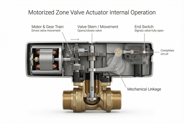
The Electrical Signal: Closing the Circuit to Signal the “End of Stroke”
Once mechanically triggered, the end switch’s dry contacts either open or close, completing or breaking an electrical circuit. This change in electrical state sends a signal to the main control panel, a boiler relay, a circulator pump, or other system components. This signal confirms that the valve has successfully completed its commanded stroke and is now in the specified position, effectively providing “proof of movement” or “end of travel” feedback.
The Sequence of Operation in Context
Consider a typical industrial heating application requesting heat:
- Thermostat/Process Controller: A “heat call” signal is initiated when temperature drops below setpoint or process demands heat.
- Valve Opens: The motorized zone valve receives power and begins to open, directing fluid flow.
- End Switch Closes: As the valve reaches its fully open position, the end switch is actuated.
- Boiler/Pump Starts: The now-closed end switch completes a circuit, signaling the boiler to fire or the circulator pump to engage, ensuring heat is only generated/distributed *after* the flow path is confirmed open.
Types of End Switches: Isolated vs. Powered
End switches typically come in two main configurations, each with specific advantages for different control system architectures.
What is an Isolated End Switch (Dry Contacts)?
An isolated end switch, often referred to as “dry contacts,” is a set of electrical contacts that are completely separate from the valve’s primary power circuit (e.g., the 24VAC that powers the actuator motor). They do not supply power but simply complete (or break) an external circuit. This is why “dry contacts” are heavily preferred in industrial instrumentation:
- Prevents Voltage Interference: They allow the valve to signal other control systems without mixing voltages or causing electrical conflicts, crucial for sensitive PLCs or safety circuits.
- Flexibility: The contacts can be wired into virtually any low-voltage control circuit, irrespective of the valve’s actuator voltage.
- Safety: Provides a clear, unambiguous signal of valve position for safety interlocks.
Integrated End Switches in HVAC Systems
While often using dry contacts, the term “integrated” sometimes refers to situations where the end switch is directly used within a specific HVAC control panel to trigger boiler or pump functions with minimal external wiring. In simpler residential or commercial HVAC applications, these switches are fundamental to sequence of operation, ensuring that the heating or cooling source doesn’t activate until the zone valve is fully open, preventing short cycling or system damage. In an industrial context, it’s the clarity and reliability of the signal from these switches that makes them invaluable for complex sequences.
Why End Switches are Critical in the Fuel Industry
For fuel industry owners, end switches are more than just a convenience; they are integral to system safety and operational integrity.
Safety Interlocks: Preventing Premature Burner Firing
One of the most vital roles of an end switch in fuel systems is to serve as a safety interlock. Imagine a scenario where a gas burner attempts to fire before its main gas valve is 100% open, or before a safety shut-off valve is properly positioned. The end switch prevents this by ensuring a “proof of closure” or “proof of opening” signal. For instance, in a burner management system, a burner will not be allowed to ignite unless the fuel line’s specific valve end switch confirms it is fully open, or if a safety shut-off valve’s end switch confirms it is fully closed, preventing a dangerous overflow or premature ignition. This real-time feedback ensures that process steps happen in the correct sequence, minimizing risks related to fuel handling. For related topics, our Gas Solenoid Valve Guide discusses how different valves handle “proof of closure” in more detail.
System Feedback: How Instrumentation Monitors Valve Health Remotely
In large industrial facilities, remote monitoring is essential. An end switch provides critical feedback to a centralized control system (like a DCS or SCADA), enabling operators to know the exact position of a valve without physically inspecting it. This real-time position status allows for:
- Diagnostic Capabilities: Highlighting if a valve is stuck or not reaching its commanded position.
- Process Optimization: Ensuring that downstream processes only start when upstream flow is confirmed.
- Alarm Generation: Alerting operators immediately if a valve fails to achieve its end of stroke, indicating potential malfunction.
Troubleshooting and Testing an End Switch
When system components aren’t synchronizing, a faulty end switch can often be the culprit. Knowing how to test it effectively is a key diagnostic skill.
Common Failure Symptoms: The Valve Opens, But the Boiler Won’t Fire
The most tell-tale sign of an end switch failure is when the motorized valve appears to operate correctly (e.g., you can see it physically move to the open position), but the associated device (boiler, pump, burner) fails to engage. This indicates that the mechanical action occurred, but the electrical signal generated by the end switch did not. Other symptoms may include intermittent operation, or system lockout without a clear valve fault.
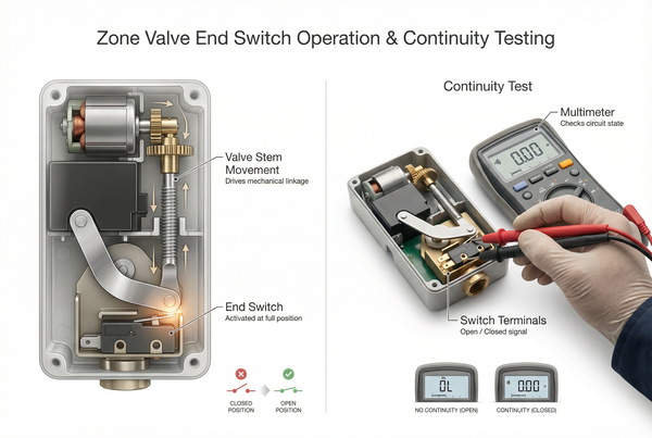
How to Test with a Multimeter: Checking for Continuity
Testing an end switch with a multimeter is straightforward:
- Safety First: Turn off all power to the zone valve and any connected equipment (boiler, pump). Lock out the power source.
- Access: Remove the actuator cover to expose the end switch terminals.
- Disconnect: Disconnect the wires leading from the end switch contacts.
- Multimeter Setup: Set your multimeter to the continuity setting (often denoted by a beep symbol or Ohms (Ω) for resistance).
- Test 1 (Valve Closed/De-energized): With the valve in its fully closed/default position, place the multimeter probes across the end switch terminals. If it’s a normally open switch, you should read “OL” or infinite resistance (no continuity).
- Test 2 (Valve Open/Energized): Manually or electrically cycle the valve to its fully open position. Once fully open, place the multimeter probes across the end switch terminals again. If the switch is functioning, you should hear a beep (continuity) or read very low resistance (close to 0 ohms).
If the continuity does not change as expected, the end switch is faulty and likely needs replacement (often part of a new actuator head).
Wiring a Zone Valve End Switch
Proper wiring of an end switch is crucial for its functionality and the safety of the entire system. While specific diagrams vary by manufacturer, core principles remain consistent.
Standard 24V Wiring Configurations
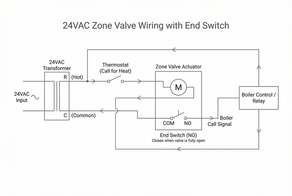
For industrial control systems, end switches are commonly integrated into a 24VAC control circuit. A typical wiring setup for a Normally Open (NO) end switch (common for triggering a boiler/pump when the valve is open) involves:
- One side of the 24VAC transformer’s secondary coil is connected to one terminal of the end switch (the “common” terminal if it’s a SPDT switch).
- The other terminal of the end switch (the “NO” terminal) is connected to the control input of the boiler, pump relay, or other device.
- The other side of the device’s control input (and the valve actuator’s power input) is connected back to the other side of the 24VAC transformer’s secondary coil (the “hot” or “unswitched” leg).
This configuration creates a series circuit where the boiler/pump won’t receive its trigger signal until the end switch closes.
Avoiding Common Wiring Errors
Incorrect wiring can lead to system malfunction or damage:
- Shorting the Transformer: Ensure you are using the correct terminals for Normally Open or Normally Closed applications and not inadvertently creating a direct short across the transformer.
- Mixing Voltages: Always ensure the control circuit’s voltage matches what the end switch and receiving device are rated for. Using dry contacts helps prevent this, but care must still be taken.
- Overloading Contacts: End switches have a maximum current rating. Ensure the load you are switching (e.g., a large relay coil) does not exceed this rating, or an intermediary relay should be used.
Frequently Asked Questions About Zone Valve End Switches
Q: Can you bypass a zone valve end switch?
Technically, an end switch can be bypassed by simply connecting the wires that would normally run through the switch. However, this is strongly discouraged for any safety-critical application. Bypassing an end switch eliminates a crucial safety interlock, meaning a boiler, pump, or burner might fire even if the valve is not correctly positioned, leading to potential equipment damage, inefficient operation, or severe safety hazards (e.g., fuel ignition without proper flow). It defeats the purpose of system synchronization and safety.
Q: Does an end switch have its own power source?
No, an end switch typically does not have its own power source. It operates as “dry contacts,” meaning it’s a simple mechanical switch that opens or closes an external circuit. It draws no power itself; instead, it completes or breaks a circuit that is powered by another source, like a 24VAC transformer that powers a boiler’s control circuit or a PLC input.
Q: What is the difference between a limit switch and an end switch?
While both are types of microswitches, their primary functions differ. An “end switch” specifically signals the completion of a valve’s stroke to fully open or fully closed. A “limit switch” is a broader term for a switch that detects the presence or absence of an object or the crossing of a certain physical limit (e.g., high-temperature limit switch on a furnace, or a limit switch on a conveyor belt detecting an item). In some contexts, a valve’s end switch could also be considered a type of limit switch, but its function is very specific to valve position feedback.
Q: Why does my zone valve end switch click but nothing happens?
If you hear the end switch click, it confirms the mechanical part of the switch is functioning and sensing the valve’s position. However, if no action occurs from the connected device (boiler, pump), the problem lies in the electrical circuit *after* the switch. This could be due to loose wiring, a broken wire downstream of the switch, a blown fuse, or a fault in the receiving device itself (e.g., a faulty boiler relay). Use a multimeter to trace continuity and voltage from the clicking switch to the next component in the circuit.
Conclusion
The end switch on a zone valve, though small, is a powerhouse of sequential control and safety in industrial fuel systems. Its reliable operation is key to efficient system synchronization, ensuring that critical components like boilers, pumps, or burners only activate when the fluid path is confirmed open or closed. For facilities operating complex systems, understanding and properly maintaining these seemingly simple devices can prevent costly downtime and enhance overall safety. To explore distinctions between manual and automated control, you might find value in our discussion of True Union Ball Valves.
Looking to automate your fuel system with high-precision instrumentation?


 English
 Arabic
 Russian
 French
 Spanish