
You’re looking at a P&ID, and there it is: that symbol for a control valve. You know it’s important, but what does it really do? Choosing the wrong one can throw your entire process into chaos, causing instability and costing a fortune in downtime.
This isn’t just theory. An incorrectly sized control valve can cause your process to oscillate wildly. The wrong type can erode in months. You end up with poor product quality, wasted energy, and a constant maintenance headache. It’s a critical decision that feels like a high-stakes guessing game.
A control valve is the final control element in a system. Think of it as the “hand” of your control loop. It takes a signal from a controller and physically manipulates the flow of a fluid to keep your process stable and on target.
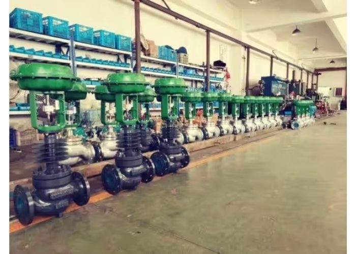
How Does a Control Loop Work?
To understand a control valve, you first need to see its place in the team. It’s part of a process control loop, which works just like the cruise control in your car or the thermostat in your house.
There are four key players:
- Sensor/Transmitter: This is the “eyes” of the loop. It measures a process variable, like temperature, pressure, or flow.
- Controller: This is the “brain.” It can be a PLC or a DCS. It compares the measurement from the sensor to your desired setpoint. If there’s a difference, it calculates what to do.
- I/P Transducer: This device converts the electrical signal from the controller (current) into a pneumatic signal (pressure).
- Control Valve (Final Control Element): This is the “hand” or “muscle.” It receives the signal from the controller and physically adjusts the flow to bring the process back to the setpoint.
Imagine you want to keep a tank’s temperature at 150°F by controlling the flow of steam. The sensor measures the temperature. The controller sees it’s 148°F. The controller sends a signal to the control valve on the steam line, telling it to open a little more. More steam flows, the temperature rises, and the loop keeps making small adjustments to hold it steady. This is a closed-loop system, and it’s the foundation of industrial automation.
What Are the Main Types of Control Valves?
Not all control valves are created equal. The type you choose depends on your process needs—precision, flow capacity, and the nature of the fluid.
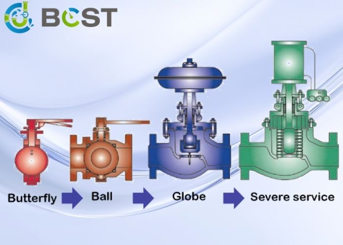
- Globe Type Control Valve: This is the workhorse for precise throttling and control. It has a linear, up-and-down motion. The fluid follows a winding path, which causes a high pressure drop but gives you excellent, fine-tuned control over the flow rate.
- Butterfly Type Control Valve: This is a rotary valve with a simple disc that turns in the flow path. It’s great for large flows, is lower in cost, and has a smaller footprint. High-performance and triple-offset versions offer much better shutoff and control than standard butterfly valves.
- V-Port / Segmented Ball Valve: This is a fantastic hybrid. It’s a rotary valve, but the ball has a v-shaped notch cut into it. This design gives it the high flow capacity of a ball valve but with the precise control characteristic of a globe valve. It’s a very popular choice for a modern control valve.
- Eccentric Plug Rotary Control Valve: This valve uses a plug that rotates and lifts off the seat, providing a direct, unobstructed flow path. It’s excellent for erosive or slurry applications where you want to minimize contact between the fluid and the valve seat.

Here’s a quick comparison of the two most common choices:
| Feature | Globe Valve | V-Port Ball Valve |
|---|---|---|
| Control Accuracy | Excellent | Very Good |
| Flow Capacity (Cv) | Lower | Higher |
| Pressure Drop | High | Low |
| Common Use | Precise Throttling | General Control, Slurries |
| Cost | Moderate to High | Moderate |
What are the Key Parts of a Control Valve?
Understanding the anatomy helps you speak the language. We can break them down into two main families.
Linear Motion Valves (like a Globe Valve):
- Body: The main housing that contains the fluid.
- Bonnet: The top part of the body that encloses the stem and packing.
- Trim: This is the collection of internal parts that control the flow. It includes the stem (connects to the actuator), the plug (moves to block the flow), and the seat (where the plug seals).
Rotary Motion Valves (like a Ball or Butterfly Valve):
- Body: The main housing.
- Shaft: The rotating part that connects to the actuator.
- Disc/Ball: The element that turns in the flow path to control it.
What About Valve Accessories?
A control valve rarely works alone. It needs a support system of accessories to function correctly.
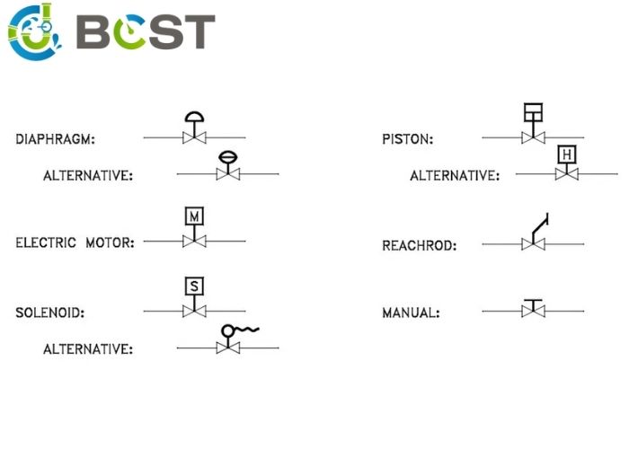
- Actuator: The muscle that physically moves the valve. Most common are pneumatic (uses air pressure), but electric and hydraulic actuators are also used.
- Valve Positioner: The actuator’s brain. It takes the control signal (e.g., 4-20mA) and ensures the valve moves to the exact position required. A positioner is essential for accurate modulating control.
- Limit Switch: An electrical switch that confirms if the valve is fully open or fully closed. It provides feedback to the control room.
- Solenoid Valve: A simple, electrically operated on/off valve used to direct air to a pneumatic actuator for on/off control.
- Air Filter Regulator: Cleans and sets the air pressure supplied to pneumatic instruments, ensuring a reliable actuator operation.
- Manual Operator (Handwheel): A gearbox or handwheel that allows you to operate the control valve manually if power or air is lost.
How to Select the Right Actuator in 6 Steps
Choosing the right actuator is just as important as choosing the right control valve. Here’s a simple, step-by-step process:
- Step 1: Identify Valve Type: Is your valve linear (globe) or rotary (ball/butterfly)? The actuator must match.
- Step 2: Check Power Source: Do you have compressed air available for a pneumatic actuator, or do you need to run power for an electric one? Pneumatic is often cheaper and faster for modulating control.
- Step 3: Consider Installation Space: Is there enough room above a globe valve for a linear actuator? Or is a more compact rotary actuator a better fit?
- Step 4: Define the Function: Is this for on/off service or modulating (throttling) control? What should happen if power fails? Fail-safe position (fail-open or fail-close) is a critical safety decision.
- Step 5: Evaluate Environment: Is it in a hazardous area that requires explosion-proof ratings? What are the ambient temperature extremes?
- Step 6: Budget: Pneumatic actuators are often less expensive upfront, but electric actuators don’t require an air supply system, which has its own costs.
What Are Some Basic Control Valve Terms to Know?
- Cv (Flow Coefficient): This is a number that tells you the valve’s flow capacity. A higher Cv means more flow can pass through the valve for a given pressure drop.
- Seat Leakage: This rating tells you how well the valve seals when it’s fully closed. ANSI Class IV is standard for many metal-seated valves, while Class VI is considered “bubble-tight.”
- Flow Characteristic: This describes the relationship between how much the valve opens and the resulting flow rate. Linear gives you an equal change in flow for each step of valve travel. Equal Percentage gives you smaller flow changes when the valve is nearly closed and larger changes as it opens more.
- Cavitation: This is a destructive phenomenon that can occur with liquids. If the pressure inside the valve drops below the liquid’s vapor pressure, bubbles form. As the pressure recovers, these bubbles collapse violently, acting like tiny hammer blows that can destroy the valve’s trim.
Frequently Asked Questions
What’s the difference between a control valve and a regular manual valve?
A manual valve is for on/off service and is operated by hand. A control valve is automated and designed to precisely throttle or modulate flow as part of a control loop, typically using a pneumatic or electric actuator.
What does a valve positioner do?
A valve positioner is a device attached to the actuator that acts like a local controller. It ensures the control valve stem is in the exact position demanded by the main controller, overcoming factors like friction and pressure imbalances.
Which control valve is best for precise throttling?
The globe control valve is generally considered the best for precise throttling applications due to its internal design, which allows for very fine and stable control over the flow rate, though at the cost of a higher pressure drop.
What does “fail-safe” mean for a control valve?
Fail-safe describes what the valve will do if its power source (air or electricity) is lost. A “fail-close” valve will shut automatically, while a “fail-open” valve will open. This is a critical safety feature determined by the process needs.
Conclusion
A control valve is far more than just a valve. It is a sophisticated instrument and the final, critical link in your automation strategy. Choosing the right valve type, sizing it correctly, and pairing it with the proper actuator and accessories is essential for a stable, efficient, and safe process.
At BCST, we help engineers navigate these choices every day. We know that the right control valve solution isn’t just about a product; it’s about understanding the entire process. Don’t guess—partner with experts who can help you make a confident decision that will serve you well for years.


 English
 Arabic
 Russian
 French
 Spanish