
Confused by complex P&ID drawings? A small symbol can cause big problems if you misunderstand it. Get it right to ensure your system’s safety and efficiency.
The non return valve symbol, also called a check valve symbol, is a graphic used in Piping and Instrumentation Diagrams (P&IDs). It shows a valve that allows fluid to flow in only one direction. This prevents backflow. The symbol’s arrow shape points in the direction of allowed flow.
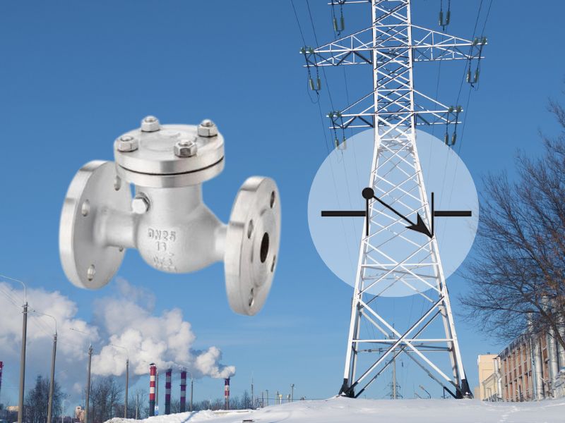
Understanding the basic symbol is the first step. But there is more to learn. These symbols have different versions that tell you important details about the valve’s type and function. Let’s look at these symbols more closely. This will make you feel sure when you read any engineering drawing. You will know exactly what the nrv symbol means and how it affects the system you are working on.
The Basic NRV Symbol and Its Common Variations
A single line drawing can look confusing. You might see a symbol and not know what it is. This can lead to design errors. Learn the common nrv symbol variations to avoid expensive mistakes.
The basic non return valve symbol is a triangle pointing in the flow direction. It often has a vertical line at its base. Variations show different valve types, like swing, lift, and ball check valves. Each symbol shows how the valve mechanism works.

Let’s go deeper into these symbols. The basic symbol is just the start. Different non-return valves work in different ways, so they have unique symbols. This helps engineers choose the right valve for a specific job. You need to know these variations to read P&IDs correctly.
Swing Check Valve Symbol
A swing check valve has a disc, or flapper, that swings on a hinge. It opens with flow and closes when flow stops or reverses. Its symbol often looks like a “Z” shape placed inside the two valve triangles, but without the triangles. The diagonal line shows the flapper. This symbol tells you the valve is good for applications where you need a full, unobstructed flow path.
Lift Check Valve Symbol
A lift check valve has a disc or piston that lifts up to allow flow. Gravity or reverse flow pressure pushes it back down to close. The symbol for a lift check valve often includes a small circle (representing a ball or piston) inside the main valve symbol, with a line showing it can move up and down. This symbol suggests the valve must be installed in horizontal lines, or in vertical lines with upward flow.
Ball Check Valve Symbol
A ball check valve uses a free-floating ball to block flow. The symbol is simple: it is a circle inside the valve body symbol. The circle shows the ball that seals the valve. This nrv symbol is common in applications with thick fluids or slurries because the ball design is less likely to get clogged.
| Valve Type | Common Symbol Description | Best Use Case |
|---|---|---|
| Swing Check | A “Z” shape or a hinged flapper inside the valve body. | Full flow, low pressure drop. |
| Lift Check | A circle or piston shape that moves vertically. | Horizontal or vertical upward flow. |
| Ball Check | A solid circle inside the valve body. | Viscous fluids and slurries. |
Reading the Non Return Valve Symbol in P&ID Diagrams
A P&ID can look like a mess of lines and symbols. It is hard to follow the process flow. You must master reading the nrv symbol to understand fluid direction and protect your equipment.
To read a non return valve symbol on a P&ID, first find the symbol on a process line. The arrow shape of the symbol always shows the allowed direction of flow. Any text or other symbols nearby give more details, like the valve’s size or materials.
Reading a P&ID is about understanding how all the parts work together. The non-return valve is a key safety component. I remember a project with Hassan, a chief engineer from Nigeria. He spotted a wrongly placed non return valve symbol on a P&ID for a pump discharge line. The symbol was facing the wrong way. If built as drawn, it would have caused massive backflow and damaged the expensive pump when it stopped. His sharp eye for detail saved the project from a big failure and a lot of money. It shows why every symbol matters.
Identifying Flow Direction
The most important job of the non return valve symbol is to show flow direction. The triangle always points in the direction the fluid is allowed to move. The line at the back of the triangle is the “wall” that stops backflow. Always follow the pipeline and confirm the symbol points away from pumps and toward the destination.
Understanding Symbol Modifiers
Sometimes, you will see extra marks on or near a symbol. A spring symbol (a small zigzag line) above the check valve symbol means it is a spring-loaded check valve. This valve can be installed in any orientation because the spring helps close it, not just gravity. Letters and numbers in a tag bubble nearby will give the valve’s unique identifier, size, and material class.
Using the Legend Sheet
Every good P&ID set comes with a legend sheet. This sheet is your dictionary for all the symbols used in the drawings. If you see an unfamiliar nrv symbol or a variation you don’t recognize, check the legend sheet first. It will define what each symbol means according to that project’s standards.
Key Standards for Non Return Valve Symbols
Using the wrong symbol standard can cause confusion between teams. Your drawings might not be understood by international partners. Following standards like ISA or ISO is very important for clear communication on any project.
The most common standards for P&ID symbols, including the nrv symbol, are ISA-5.1 and ISO 14617. These standards give a consistent set of symbols for instruments and valves. They ensure drawings are understood everywhere, across different companies and countries.
Why do standards matter so much? Because engineering is a team effort. A plant might be designed in one country, with equipment from another, and built in a third. Everyone needs to read the same language on the drawings. Standards provide this common language. Without them, a simple symbol could be misunderstood, leading to safety risks or operational failures. My father always taught me that a good valve is useless if it’s put in the wrong place. Clear standards on drawings prevent that.
The ISA-5.1 Standard
The Instrumentation, Systems, and Automation Society (ISA) standard ISA-5.1 is very popular, especially in North America and in the oil and gas industry. It provides a comprehensive set of symbols. Its general check valve symbol is the familiar triangle with a line. It also provides symbols for specific types like swing, lift, and diaphragm check valves, though they are often simplified.
The ISO 14617 Standard
The International Organization for Standardization (ISO) provides ISO 14617, which is more common in Europe and other parts of the world. Its symbols are often very similar to ISA’s, but there can be small differences. For example, the way a symbol is modified to show it is spring-loaded might look slightly different. The key is to know which standard a project uses and stick to it.
| Feature | ISA-5.1 | ISO 14617 |
|---|---|---|
| General Symbol | Triangle pointing with flow, vertical line at base. | Very similar, sometimes just an open triangle on a line. |
| Spring-Loaded | Often shown with a diagonal line and a spring symbol. | May have a specific symbol modifier defined in the standard. |
| Main Use | Widely used in the Americas, oil and gas. | Widely used in Europe, general process industries. |
Selecting the Correct Non Return Valve Symbol for Your Design
Choosing a generic symbol seems easy, but it hides important details. This can lead to the wrong valve being ordered for the job. You must select a symbol that shows the valve’s function accurately.
Choose the non return valve symbol that best matches the valve’s internal mechanism. Use a swing check symbol for low-pressure drop needs. Use a lift check symbol for horizontal lines. Or use a ball check symbol for thick fluids. The symbol choice communicates your design needs clearly.
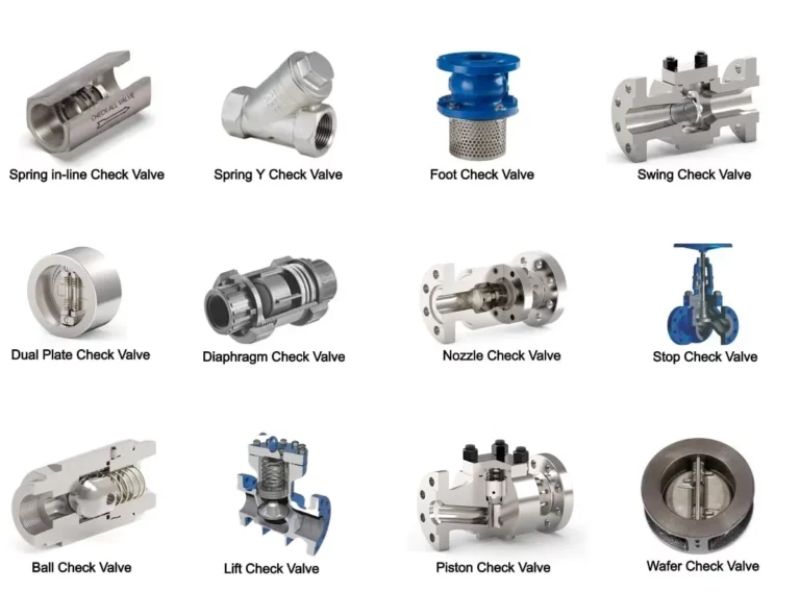
When you are designing a system, you are not just drawing lines and symbols. You are making decisions that affect how the plant will run for years. Selecting the right valve type is critical. The symbol you put on the P&ID is your instruction to the people who will build and operate the plant. A generic symbol is a lazy instruction. A specific symbol is a clear, professional one. It ensures the right hardware is installed to match the process conditions you designed for.
Symbol for High-Pressure Applications
In high-pressure systems, like on the discharge of a reciprocating pump, you need a valve that can handle pressure spikes and close quickly. A nozzle check valve or a piston check valve is often used. These have specific symbols that are different from a standard swing check. Using the correct symbol ensures the procurement team buys a valve that will not fail under pressure.
Symbol for Vertical Flow
If you have a pipe going straight up, you cannot use a standard lift check valve that relies on gravity to close. You need a spring-loaded check valve. You must use the symbol for a spring-loaded check valve. This tells the installers that this valve will work in a vertical line. A simple mistake here could lead to the system not working at all.
Symbol for Preventing Water Hammer
Water hammer happens when flow stops too quickly, causing a damaging shockwave. In large water lines, this is a big risk. A silent check valve or a nozzle check valve is designed to close fast but smoothly to prevent this. Using the specific symbol for these valves on your P&ID is a critical safety instruction. It shows you have thought about the system’s dynamics.
Using Symbols for Valve Installation and Troubleshooting
A valve is installed, but the system is not working right. Was it installed backward? The P&ID and the valve’s own markings are your guide to fixing the problem fast.
During installation, you must compare the flow arrow on the actual non-return valve body with the direction shown by the nrv symbol on the P&ID. If they do not match, the valve is backward. This symbol is your main guide for correct orientation.
The P&ID is not just a document for designers. It is a vital tool for the construction and maintenance teams. When I started in my family’s factory, I spent months on the assembly floor. I learned that every valve has a flow arrow cast or stamped onto its body. This arrow must match the flow direction on the P&ID. It seems simple, but getting it wrong is a common and costly mistake. The drawing tells you the “what” and “where,” and the physical arrow on the valve confirms it.
Verifying Installation Direction
This is the most common issue. A non-return valve installed backward will completely block flow in the intended direction. Before starting up any new line, a good technician will walk the line, P&ID in hand, and check that every non-return valve is pointing the right way. The symbol on the drawing is their map for this check.
Troubleshooting Common Issues
What if the valve is installed correctly, but you still have problems?
- Valve Chatter: If you hear a rapid banging noise from the valve, it could be “chatter.” This often happens if a swing check valve is used in a line with pulsating flow, like after a compressor. Looking at the P&ID, you can see the valve type from the symbol and its location. This helps you realize the wrong type of valve was chosen for that service.
- Leakage: If the valve is not sealing properly and allowing backflow, it could be damaged or fouled. The P&ID tells you the valve’s tag number. You can use this to check the maintenance records and see if it is the right type of valve for the fluid. Some fluids require soft-seated valves to seal properly, and the P&ID specification should reflect this.
Non Return Valve Symbols in Different Industries
You might work in the food industry, but your drawings look like those from oil and gas. Are the symbols the same? Understanding industry-specific uses prevents confusion and makes sure you follow the rules.
While the basic non return valve symbol is universal, how it’s used is different. In water treatment, it prevents dirty water from mixing with clean water. In oil and gas, it protects high-pressure equipment. In HVAC, it makes sure hot or cold water circulates correctly.
The beauty of P&ID symbols is their flexibility. A single symbol can represent a tiny plastic check valve in a medical device or a huge metal valve in a dam. The context of the drawing tells you the story. The process lines, equipment, and notes on the P&ID all give clues about the valve’s importance, material, and specific function within that industry. It’s like a language where the same word can have different meanings based on the conversation.
Oil and Gas Applications
In the oil and gas industry, safety is everything. Non-return valves are critical safety barriers. They prevent blowouts by stopping the reverse flow of high-pressure oil and gas. Here, the P&IDs are very detailed. The non return valve symbol will be part of complex systems like High-Integrity Pressure Protection Systems (HIPPS). The symbol must be clear and accurate to ensure these safety systems are designed and installed correctly.
Water Treatment Plants
In water and wastewater treatment, the main concern is preventing contamination. Non-return valves stop used water from flowing back into the clean water supply. They also protect pumps from backflow when they are turned off. The symbols used here are standard, but the materials of the actual valves are key. The P&ID specifications linked to the symbol will call for corrosion-resistant materials like stainless steel or PVC.
HVAC Systems
In Heating, Ventilation, and Air Conditioning (HVAC) systems, non-return valves (often called flow checks) are used in hydronic systems. They ensure that hot or chilled water flows to the right parts of a building and does not short-circuit the system. For an HVAC technician, seeing the check valve symbol on a drawing immediately tells them where to look for problems related to poor circulation or heating/cooling in the wrong zones.
Frequently Asked Questions (FAQ)
Q1: What is the main difference between a non-return valve symbol and a regular valve symbol? A: A regular valve symbol (like for a gate or ball valve) is usually symmetrical, showing it can control flow in either direction. A non return valve symbol is asymmetrical, with a triangle or arrow shape that clearly indicates flow is only allowed in one direction.
Q2: Can a single P&ID use symbols from different standards? A: This is not a good practice. It can cause a lot of confusion. A project should always define one standard (like ISA-5.1 or ISO 14617) in the project documents and use it consistently across all P&IDs to ensure clarity and safety.
Q3: What does a spring-loaded non return valve symbol look like? A: It looks like a standard nrv symbol but with an added zigzag line, which represents a spring. This modifier is usually drawn on top of or next to the main symbol, indicating the valve has a spring to help it close.
Q4: Is the nrv symbol the same as a check valve symbol? A: Yes, they are the same. “Non-return valve” (NRV) and “check valve” are two names for the same device. Therefore, the nrv symbol and the check valve symbol are identical and used interchangeably.
Q5: Why is the flow direction so important for a non return valve symbol? A: The entire purpose of a non-return valve is to control flow direction. If the symbol is drawn backward on the P&ID, the valve will be installed backward. This will either block flow completely or fail to prevent backflow, potentially causing equipment damage or system failure.
Q6: Where can I find a complete list of P&ID symbols? A: You can find complete lists in the official standard documents, such as ISA-5.1 (“Instrumentation Symbols and Identification”) or ISO 14617 (“Graphical symbols for diagrams”). Many engineering handbooks and online resources also provide comprehensive symbol libraries based on these standards.
Conclusion
Mastering the non return valve symbol is essential for any engineer or technician. It helps you ensure safe, efficient, and accurate system design, installation, and operation every day.


 English
 Arabic
 Russian
 French
 Spanish