

Are you Really Maintaining your Ball Valve? The Hidden Danger of Trapped Liquid
You’ve confidently closed a válvula de bola in a cryogenic pipeline, creating what you believe is a safe isolation. But trapped inside the valve’s sealed cavity, a small amount of liquid is silently warming up, turning into a high-pressure bomb. According to a research, For common hydrocarbons or water, heating a fully trapped volume by only 10–20 °C can raise pressure well above typical piping design limits (e.g., >200 bar in small rigid cavities). Engineering literature and CFD studies on safety valves show that small displacements in a constrained liquid cause very large pressure forces on valve internals.
This is the “ball valve effect,” a dangerous phenomenon where trapped liquid heats up and expands, generating immense pressure that can exceed the valve’s rating and cause a catastrophic rupture. This is prevented by providing a pressure relief path from the valve’s body cavity.
How Does Liquid Expansion Generate So Much Pressure?
You know that heating a liquid makes it expand, but you’re wondering how it can create enough force to destroy a solid steel valve.
When a cryogenic liquid like LNG is trapped and heated, it doesn’t just expand; it boils and turns into a gas, increasing its volume by up to 600 times. In the sealed, fixed-volume cavity of a ball valve, this massive expansion translates directly into a rapid, unstoppable pressure increase that can easily exceed 10,000 PSI.
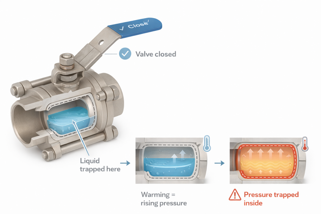
The Physics behind a Pressure Bomb
To an engineer like Hassan, who deals with the immense energy stored in liquefied gases, understanding this phenomenon is a matter of process safety. The principle is simple, but the consequences are severe. It’s a direct application of thermodynamic laws in a scenario where they can work against you.
The Phase Change Multiplier
Every liquid has a liquid-to-vapor expansion ratio. For water turning to steam, it’s significant. For cryogenic liquids, it is enormous.
- Liquid Nitrogen (LN2): 1-to-694 expansion ratio.
- Liquefied Natural Gas (LNG): 1-to-600 expansion ratio.
- Liquid Oxygen (LOX): 1-to-860 expansion ratio.
Now, consider the process step-by-step:
- Trapping: A standard trunnion or floating ball valve is closed in a cryogenic line. The ball rotates, and the upstream and downstream seats create a bubble-tight seal. A small volume of cryogenic liquid, perhaps only a few cubic inches, is now trapped in the enclosed cavity between the ball and the valve body.
- Heating: The pipeline, though insulated, is never perfect. Ambient heat from the outside environment slowly conducts through the valve body and warms the trapped liquid.
- Boiling: As the liquid’s temperature rises past its boiling point (-162°C for LNG), it begins to vaporize inside the sealed cavity.
- Pressure Buildup: The resulting gas has nowhere to go. According to the Ideal Gas Law (PV = nRT), as more liquid turns to gas (increasing ‘n’) and the temperature (‘T’) rises in a fixed volume (‘V’), the pressure (‘P’) must increase dramatically.
- Failure: A typical ASME Class 150 valve might be rated for about 285 PSI. The pressure generated by vaporization can quickly reach thousands, or even tens of thousands, of PSI. This pressure will find the weakest point of the valve—often the body wall or bonnet joint—and cause a violent rupture, sending metal fragments flying.
This isn’t a slow leak; it’s a sudden, explosive release of energy, which is why preventing it is a non-negotiable aspect of cryogenic system design.
What Is the Most Common Way to Prevent the Ball Valve Effect?
You are designing a system and need to make sure the ball valves are safe for liquid service. You need a reliable and straightforward solution.
The most common and effective solution is to specify a vented ball. This involves drilling a small hole in the upstream face of the ball, which provides a continuous path for any overpressure in the cavity to bleed safely back into the upstream side of the pipeline.
A Comparison of Relief Solutions
While a vented ball is the most common solution, it’s not the only one. For an engineer like Hassan, choosing the right method depends on the specific application, whether the flow is unidirectional, and maintenance considerations.
1. The Vented Ball
This is the workhorse solution for preventing the ball valve effect.

- How it Works: A small hole (typically 1/8″ or 1/4″) is drilled from the ball cavity through to the upstream face of the ball. When the valve is closed, this hole allows any pressure building in the cavity to escape upstream.
- Critical Installation Detail: The valve becomes unidirectional. It debe be installed with the vented side facing the upstream pressure source. If installed backward, the hole faces the downstream side. When the valve is closed, the cavity is still sealed from the upstream pressure, and the dangerous pressure buildup can still occur. For this reason, all vented ball valves are clearly marked with a flow arrow.
- Pros: Simple, passive, low-cost, and highly reliable.
- Contras: Valve is unidirectional. Incorrect installation negates the safety feature.
2. Self-Relieving Seats
This is a more advanced solution that maintains bi-directional flow.
- How it Works: The upstream seat is designed with a special profile. A small lip or engineered cut allows the seat to act like a check valve. If the cavity pressure becomes slightly higher (e.g., 10-20 PSI) than the upstream line pressure, it pushes the seat back just enough to break the seal and vent the excess pressure upstream.
- Pros: Allows the valve to be bi-directional, eliminating the risk of incorrect installation. The valve can seal against pressure from either direction.
- Contras: More complex and expensive seat design. May have very specific sealing characteristics that need to be understood for the application.
3. External Body Cavity Relief Valve
This solution involves fitting a miniature pressure relief valve directly onto the body of the ball valve.
- How it Works: A small mechanical spring-loaded relief valve is threaded into a port on the valve body. If the cavity pressure reaches the set point of the relief valve, it opens and vents the pressure to the atmosphere.
- Pros: Provides an external, visible, and testable relief device. Its function is not dependent on valve orientation.
- Contras: Vents process fluid to the atmosphere, which is unacceptable for hazardous or flammable liquids like LNG. Adds an external component that can be a leak path or be damaged. Highest cost option.
| Relief Method | Dirección del caudal | Pros | Cons |
|---|---|---|---|
| Vented Ball | Unidirectional | Simple, low cost, reliable | Risk of incorrect installation |
| Self-Relieving Seats | Bidireccional | Eliminates installation error | More expensive, complex seat |
| External Relief Valve | N/A | Externally testable | Vents to atmosphere, adds leak path |
For most cryogenic and liquid thermal expansion applications, the vented ball provides the most robust and cost-effective safety solution, provided strict installation procedures are followed.
Conclusión
The ball valve effect is a critical safety risk in liquid and cryogenic service. However, it is easily prevented by using a vented ball or other pressure relief feature to ensure trapped liquid can never cause a catastrophic pressure buildup.
Ensure the Safety of Your Cryogenic System.
Specify the right pressure relief feature for your ball valves. Contact our engineers for expert guidance.


 English
 Arabic
 Russian
 French
 Spanish