
Staring at a complex engineering drawing and feeling completely lost? You need to understand your plant’s roadmap, but the strange symbols are like a foreign language, and a single mistake can be costly.
A Piping and Instrumentation Diagram (P&ID) uses a standardized set of P&ID valve symbols to represent every valve in your system. Learning this visual language is the first step to understanding, operating, and maintaining your process safely and efficiently.
When I first started in my father’s valve business, I would look at these diagrams and see a chaotic mess of lines and circles. But my father taught me to see them as a story. Each line is a pipe, and each symbol is a character with a specific job. An experienced chief engineer I work with, Hassan, calls them the “single source of truth” for his entire plant. Let’s break down this language so you can read the story, too. Together, we’ll learn these crucial P&ID valve symbols.
What are the most common P&ID valve symbols you must know?
Ever worried about confusing a simple válvula on/off with a throttling valve? This small mistake on a P&ID can lead to major operational problems. Knowing the basics is not optional, it’s essential for safety.
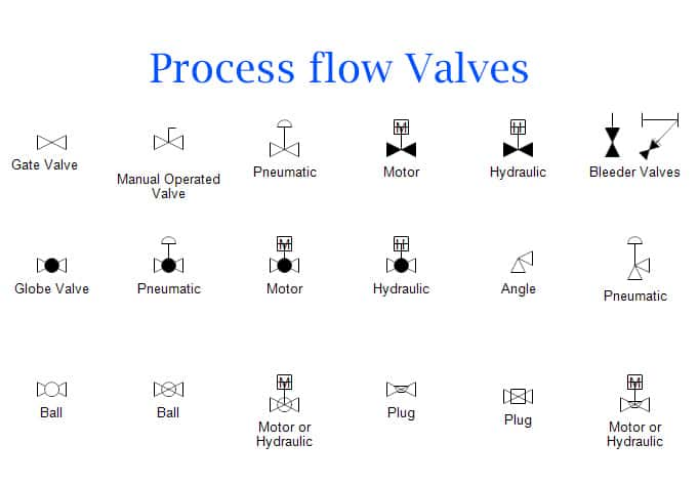
The most common P&ID valve symbols you’ll see are for two-way valves like gate, globe, and ball valves. Their base symbol is two triangles pointing at each other. Small additions to this base symbol tell you exactly what kind of valve it is.
Dive Deeper: The Building Blocks of P&ID Language
Learning to read these diagrams starts with the basics. Think of the base symbol—two triangles pointing inward on a line—as the generic symbol for any 2-way valve. It’s the starting point. From there, we add small details to identify the specific type. This visual shorthand is what makes P&IDs so powerful. If you know the code, you can understand a complex system at a glance. These details are the most important P&ID valve symbols to learn first.
When I work with Hassan on new project plans, the very first thing he does is scan the P&IDs for these fundamental symbols. He needs to quickly identify the isolation points (gate valves) and the control points (válvulas de globo). The clarity of the P&ID valve symbols allows him to do this in minutes, not hours.
From Generic to Specific
Let’s look at how this works. It’s a simple, logical system once you see the pattern.
| Tipo de válvula | Symbol Modification | Función principal |
|---|---|---|
| Generic 2-Way Valve | (None) | A simple placeholder. |
| Válvula de compuerta | A vertical line between the triangles. | Simple On/Off isolation. Not for throttling flow. |
| Válvula de bola | An open circle between the triangles. | Quick On/Off action. Can be used for some throttling. |
| Válvula de globo | A filled-in, solid circle between triangles. | Precise flow control (throttling). |
You can see how a small change in the P&ID valve symbols completely changes the valve’s purpose. Mistaking a globe valve symbol for a gate valve symbol could mean you install an expensive control valve where a simple, cheap isolation valve was needed. It’s a costly error that Hassan has seen happen when junior engineers aren’t properly trained to read these essential P&ID valve symbols.
How do symbols show if a valve is open or closed, and what powers it?
Is a valve supposed to be open or closed during normal operation? What happens if the power fails? The P&ID holds the answers, but the little shapes on top of the valve symbols can be confusing.
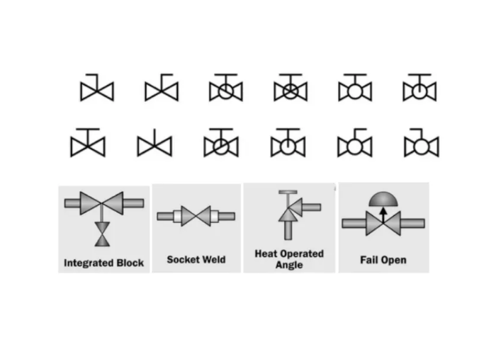
P&ID valve symbols use additional icons to show actuator type (what powers the valve) and its normal or fail-safe position. A half-moon shape on top shows it’s a diaphragm actuator, while an “M” in a circle means it’s an electric motor.
Dive Deeper: Indication, Actuation, and Failsafes
A valve is useless without a way to open or close it. This is its “actuation.” A simple handwheel for manual operation is the most basic, but in automated plants, we use actuators powered by air, electricity, or oil. The P&ID valve symbols for these actuators are just as important as the valve symbol itself. They tell you what utilities are needed to make the valve work.
Furthermore, we need to know the valve’s state. A shaded-in symbol often means “Normally Closed” (NC), while an unshaded one means “Normally Open” (NO). For automated valves, we are most concerned about what it does when power is lost. This is the “fail-safe” position.
- FO (Fail Open): The valve opens on loss of power.
- FC (Fail Close): The valve closes on loss of power.
I remember a project with Hassan for a chemical dosing system. They were injecting a corrosive chemical into a water line. He was adamant that the control valve must be “Fail Close.” He explained, “If we lose instrument air, I cannot have this valve fail open and dump raw chemical into the system. It must shut safely.” This critical safety instruction was communicated with just two letters, “FC,” next to the P&ID valve symbols for the control valve. Without that note on the P&ID valve symbols, a supplier might have provided the wrong configuration, creating a huge safety risk.
Common Actuator Symbols
| Actuator Type | Common Symbol | Cómo funciona |
|---|---|---|
| Manual | A ‘T’ shape on the valve stem | Handwheel operated by a person. |
| Pneumatic Diaphragm | A half-moon shape over the stem | Uses compressed air to push a flexible diaphragm. |
| Motor eléctrico | The letter ‘M’ inside a circle | Uses an electric motor and gears to turn the valve stem. |
| Solenoid | The letter ‘S’ inside a square | An electromagnetic coil that quickly opens or closes a small valve. |
Estos P&ID valve symbols give you a complete picture of not just what the valve is, but cómo it works within the greater control system.
Are P&ID valve symbols the same everywhere in the world?
Ever looked at a drawing from a different company and noticed the symbols are slightly different? This can cause confusion and dangerous misunderstandings, especially in international projects.
While most companies base their P&ID valve symbols on the ISA-5.1 standard, there are no strict global rules. Large companies often create their own detailed legends. Always check the legend sheet on a P&ID drawing first to understand their specific symbols.
Dive Deeper: The Importance of the Legend Sheet
The ISA-5.1 standard from the International Society of Automation provides a great foundation. Most P&ID valve symbols you see will come from this standard. However, it’s a guideline, not a law. My family’s company supplies valves for projects all over the world, and I’ve seen dozens of variations.
Hassan works for a major multinational corporation. They have their own internal engineering standards that are thicker than a phone book. Their standard for P&ID valve symbols is based on ISA-5.1 but includes many more specific symbols for specialized equipment they use. Any contractor who wants to work with them must learn and use their specific symbols.
Why the Legend is Your Best Friend
When you receive a set of drawings, the first page you should look for is the legend. This page is your dictionary. It defines every symbol, line type, and abbreviation used in that specific set of P&IDs. Never assume a symbol means what you think it means.
Here’s why this is critical:
- Clarity: It removes all doubt. You can see exactly what the designer intended. A weird-looking symbol for a check valve is fine, as long as it’s clearly defined in the legend.
- Consistency: It ensures everyone on the project—engineers, fabricators, operators, and maintenance—is speaking the same language. This prevents costly construction mistakes.
- Seguridad: Most importantly, it prevents dangerous misinterpretations. You’ll know for sure if a symbol represents a simple check valve or a complex pressure-relief valve, two devices with very different but critical safety functions.
I always tell my clients, “Don’t just look at the P&ID valve symbols on the main drawing; study the legend first.” It’s a simple habit that has saved me and my clients from countless problems. It ensures that the story the P&ID tells is the one everyone understands. These P&ID valve symbols are only useful if everyone agrees on what they mean.
FAQs
1. What is the P&ID symbol for a basic valve?
It’s two triangles on a line pointing towards each other. This is the base for most common valve symbols.
2. How do you show a normally closed valve on a P&ID?
En P&ID valve symbols for normally closed valves are often shaded in or colored black.
3. What does the ‘S’ mean on a P&ID valve symbol?
An ‘S’ inside a box above the valve indicates it is operated by a solenoid.
4. Where can I find the official list of P&ID valve symbols?
The ISA-5.1 standard is the primary reference, but always check the drawing’s legend sheet first.
Conclusión
Learning P&ID valve symbols turns confusing diagrams into clear roadmaps. It’s the language of our industry, essential for building, operating, and maintaining processes safely and efficiently. Master it.


 English
 Arabic
 Russian
 French
 Spanish