
How to Wire a Zone Control Valve: A Technician’s Guide
In the intricate world of hydronic HVAC systems, accurate wiring of zone control valves is not just a best practice—it’s paramount for system efficiency, comfort, and longevity. Mismatched connections or improper installations can lead to zones that never heat or cool, short-cycling equipment, and unnecessary service calls.
This practical guide from BCST Valve provides HVAC technicians with clear, step-by-step instructions and essential schematics for correctly wiring zone control valves. Building on our Complete Guide to Zone Control Valves for HVAC Systems, we’ll move beyond the theoretical to the hands-on, ensuring your installations are robust and reliable from the start. We’ll cover fundamental concepts, common scenarios, and critical considerations for a flawless setup.

Safety First: Essential Precautions
Working with electrical systems always carries risks. Before beginning any wiring work, prioritize safety:
- Disconnect Power: Always turn off the power at the main breaker or fuse panel to the entire HVAC system before touching any wiring. Verify with a voltmeter.
- Lockout/Tagout: For commercial or industrial settings, follow proper lockout/tagout procedures.
- Personal Protective Equipment (PPE): Wear appropriate PPE, including insulated gloves and safety glasses.
- Consult Local Codes: Always adhere to local electrical codes and regulations.
Understanding the Key Players in Your Wiring Loop
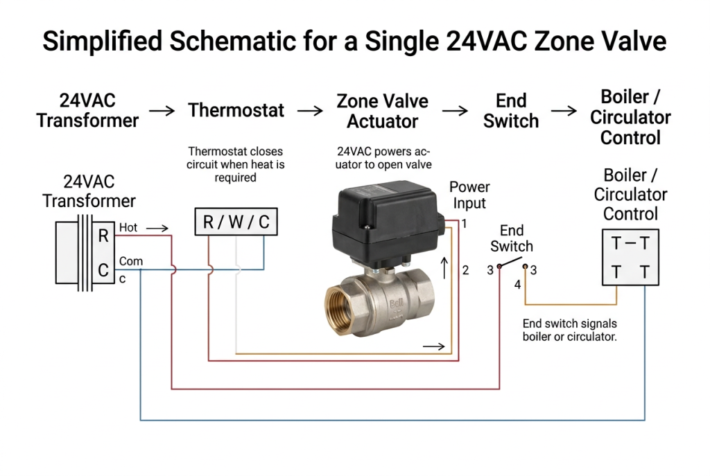
Every zone control valve installation involves a few core components working in harmony. A brief review of their roles will clarify the wiring logic:
- Transformer: Typically a 24VAC step-down transformer that provides low-voltage power for the control circuit.
- Thermostat: The brain of the zone, sensing temperature and sending a call for heating/cooling to the zone valve.
- Zone Valve Actuator: The electro-mechanical part of the zone valve that receives the thermostat signal and physically opens/closes the valve.
- Zone Valve End Switch: An internal switch within the actuator that closes (or opens) when the valve is fully actuated, signaling the boiler or circulator to energize.
- Boiler/Circulator Control: The main heating appliance or pump that receives the signal from the end switch and provides conditioned fluid.
For a detailed breakdown of how actuators and end switches function, refer to our article: How a Zone Valve Works: Actuators, End Switches, and Schematics.
Basic Wiring: Single Zone Valve Installation
Let’s start with the most common scenario: wiring a single, typical 24VAC power-open/spring-return zone valve in a hydronic heating system. Most such valves (e.g., Honeywell, Taco, Caleffi) follow a similar color-coding convention, though always consult the manufacturer’s specific instructions.
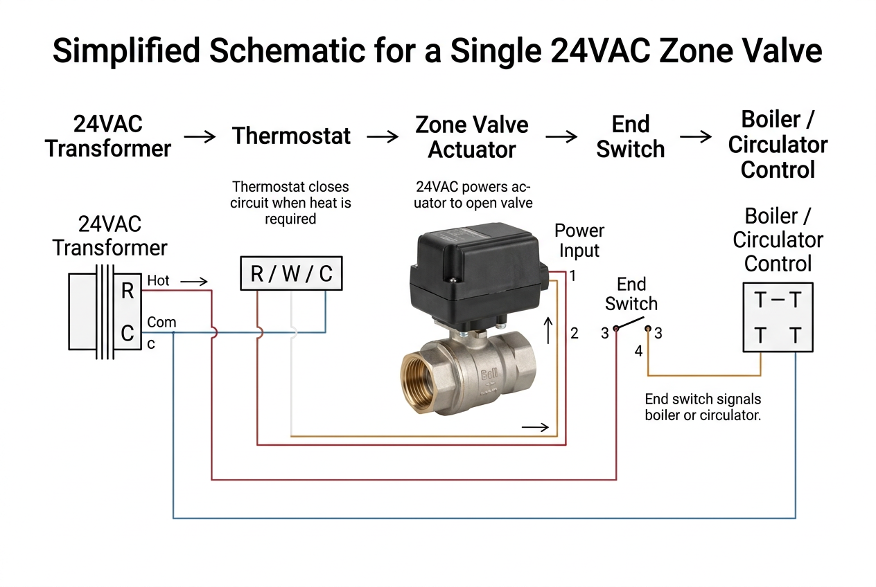
Step-by-Step Wiring Procedure:
- Transformer Connection:
- Connect one side of the 24VAC transformer’s secondary (e.g., ‘C’ or common) to one of the two terminals on the thermostat (usually ‘C’ or ‘B’).
- Connect the other side of the 24VAC transformer’s secondary (e.g., ‘R’ or hot) to the power input terminal of the zone valve actuator (often a Red or Yellow wire, sometimes labeled ‘1’ or ‘TR’).
- Thermostat to Actuator:
- Connect the ‘W’ (Heat call) terminal of the thermostat to the other power input terminal of the zone valve actuator (often a White or Yellow wire, sometimes labeled ‘2’ or ‘TH’). This completes the circuit to energize the actuator when the thermostat calls for heat.
- End Switch to Boiler/Circulator:
- Identify the two end switch terminals on the zone valve actuator (often two Orange wires, or labeled ‘3’ and ‘4’).
- Connect one of these end switch terminals to one side of the 24VAC signal input on your boiler’s control panel or external circulator relay (e.g., one of the ‘T’ terminals on a boiler control).
- Connect the other end switch terminal back to the ‘R’ (hot) side of your 24VAC transformer.
- Alternatively: If a single transformer powers multiple zone valves, the second end switch terminal often connects to the common ‘C’ terminal of the overall zone control panel’s transformer, and the ‘T’ terminals on the boiler tie to the zone panel’s respective outputs.
Wiring Multiple Zones with a Zone Control Panel
For systems with multiple zones, directly wiring each valve and thermostat to the boiler can become cumbersome. This is where a dedicated zone control panel (or zone board) simplifies wiring and centralizes control.
- Zone Panel Input: Each thermostat (R, W, Y, G, C depending on system) connects directly to specific terminals on the zone control panel.
- Zone Valve Output: Each zone valve actuator (power wires) connects to a corresponding numbered zone output on the panel.
- End Switch Integration: The end switch wires from each zone valve also connect back to designated terminals on the zone panel. The panel then aggregates these signals.
- Main System Control: The zone control panel has dedicated outputs that connect to the boiler’s ‘T’ terminals (for heat call) and the circulator pump relay. The panel ensures the boiler and pump only activate when at least one zone valve is fully open and calling for heat.
Zone boards greatly streamline multi-zone installations, provide built-in transformers, and manage sequence of operations for multiple circulators or staging boilers.
Variations and Important Considerations
Normally Open (NO) vs. Normally Closed (NC) Valves
Most zone valves are Normally Closed (NC), meaning they are closed when de-energized and open when power is applied to the actuator. However, some applications (e.g., cooling systems where a loss of power should result in maximum cooling for safety) might use Normally Open (NO) valves, which are open when de-energized and close when power is applied. Always verify the valve’s default state before wiring.
Power-Open/Power-Close (POP) Actuators
While spring-return actuators are common, some valves use Power-Open/Power-Close (also known as “two-way” or “floating” control) actuators. These require continuous power to one terminal to open and another terminal to close, without a spring return. Wiring for these is typically more complex, involving motor relays or specialized controllers, and will differ significantly from the basic schematic above.
C-Wire (Common Wire) for Thermostats
Many modern programmable or smart thermostats require a continuous 24VAC common (‘C’ wire) connection to power their internal electronics. Ensure your transformer and wiring provide this if using such thermostats, or they may experience battery drain or intermittent operation.
Testing and Verification
Once wired, it’s crucial to test each zone individually:
- Apply Power: Carefully re-energize the system.
- Thermostat Call: Set each thermostat to call for a temperature significantly above ambient (for heating) or below (for cooling).
- Observe Actuator: Watch for the valve actuator to move and listen for any operational sounds. Depending on the type, this can take 30 seconds to 2 minutes.
- Verify Heat Source Activation: Confirm that the boiler or circulator activates once the zone valve is fully open.
- Check for Flow: Feel the pipes around the zone for the presence of heated or cooled water.
Common Wiring Mistakes and Troubleshooting Tips
Even experienced technicians can sometimes make simple wiring errors. Common mistakes include reversed polarities, incorrect end switch connections, or overloaded transformers. If a zone isn’t functioning as expected, start by re-checking each connection against the manufacturer’s diagram. If issues persist, our detailed guide on diagnosing problems can help:
Need Help Diagnosing Issues?
For a comprehensive breakdown of diagnosing common zone valve issues, including those stemming from wiring errors, consult our Field Guide to Troubleshooting Zone Control Valve Failures.
Conclusion: The Foundation of Reliable Control
Properly wiring a zone control valve is the foundation upon which an efficient and responsive hydronic HVAC system is built. By meticulously following wiring diagrams, understanding the roles of each component, and adhering to safety protocols, technicians ensure that every zone operates precisely as intended, delivering optimal comfort and energy savings.
At BCST Valve, we design our zone control valves for straightforward installation and dependable performance, empowering technicians to deliver high-quality, reliable climate control solutions. Trust BCST to provide the robust components you need for every wiring challenge.
Seeking high-quality, easy-to-wire zone control valves?


 English
 Arabic
 Russian
 French
 Spanish