
Common Gas Accessory Introduction
Traffic Parameters Of Commonly Used Attachments
Common Gas Source Pipe Flow Parameters
| Specification | Circulation Area (mm²) | CV Value | Compressed Air Flow Rate (NL/min) |
|---|---|---|---|
| ф8 Gas Source Pipe | 28 | 1.57 | 392 |
| ф10 Gas Source Pipe | 50 | 2.8 | 698 |
| ф12 Gas Source Pipe | 78.5 | 4.36 | 1090 |
| ф16 Gas Source Pipe | 153.8 | 8.5 | 2125 |
Note: CV = 1, Flow area = 18mm², Compressed air flow rate = 250NL/min. The wall thickness of the gas source pipe is "hmm".
Positioner Model & Output Flow
| Positioner Model | Output Flow (NL/min) |
|---|---|
| SIEMENS PS2 Series | 110 |
| DVC6000 Series | 170 |
Introduction To Commonly Used Attachments
Pressure Reducing Valve
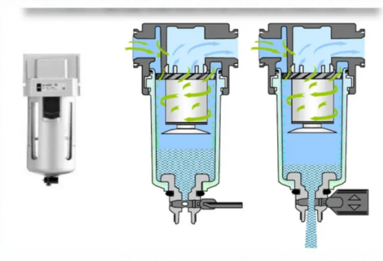
The air filter pressure reducing valve is generally installed in front of the pneumatic control instrument. It filters and purifies compressed air while adjusting the air source pressure to the required value for pneumatic instruments. It provides clean air sources of different pressures for pneumatic instruments.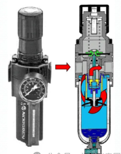
Pneumatic Amplifier
Overview
A pneumatic amplifier is a high-capacity air relay that increases the actuator’s response speed and reduces time lag. It is especially useful when transmitting signals over long distances or when actuators have a large capacity.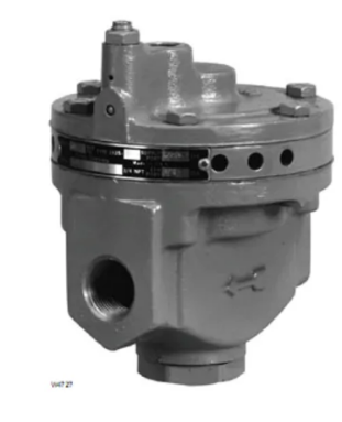
Structure & Working Principle
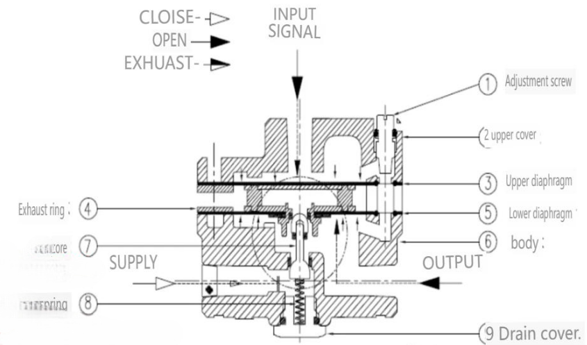
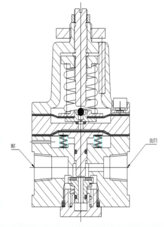
The pneumatic amplifier adjusts output pressure based on signal pressure. It consists of a diaphragm, valve core, and adjustment screw to regulate pressure output, ensuring system stability.
Retaining Valve (Locking Valve)
Function
Used in conjunction with a pneumatic valve and positioner to maintain valve position in case of air source failure.
Structure & Operation
When air pressure drops below a set threshold, the valve locks the actuator position to maintain process stability until the air supply is restored.
Two-Position Three-Way Air Control Valve
Structure & Working States
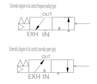
- Normally Closed Connection: IN (air pressure input), OUT (pressure output), EXH (pressure exhaust), PILOT (pilot pressure input).
- Normally Open Connection: EXH (air pressure input), IN (output), OUT (pressure output), PILOT (pilot pressure input).
Two-Position Five-Vent Control Valve
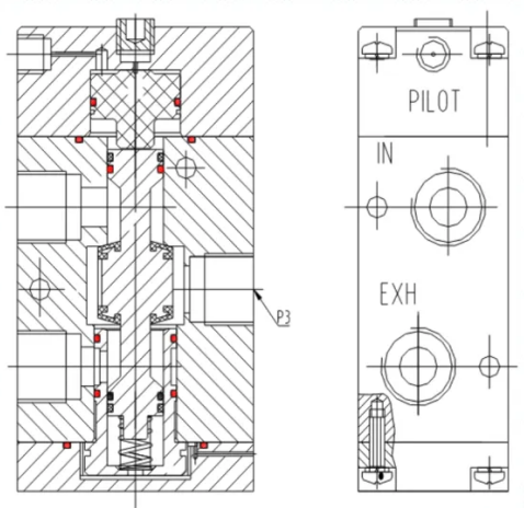
Structure & Working States
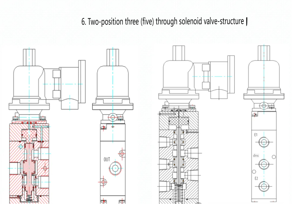
- SUP (air pressure input), AB (pressure output), E1, E2 (pressure exhaust ports), PILOT (pilot pressure input).
- The control valve operates by changing pilot pressure to regulate airflow between input and output ports.
Two-Position Five-Way Solenoid Valve
Function
Controls air pressure direction through electromagnetic activation.
Working Status
- When powered: Air flows from SUP to A, while SUP to B is blocked.
- When unpowered: Air flows from SUP to B, while SUP to A is blocked.
Flow Control Valve
Controls gas flow in pipelines to regulate actuator movement speed. Consists of a tapered tip valve seat and adjustment bolts to manage the flow rate.
Positioner
Function
Converts electrical signals (4-20mA) into pneumatic signals (20-100kPa) to drive actuators.
Components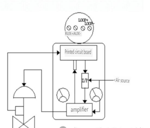
- I/P Converter: Converts electrical signals to pneumatic signals.
- Control Panel: Processes input signals and executes control calculations.
- Amplifier: Amplifies I/P signal for actuator response.
- Stroke Sensor: Provides real-time valve position feedback.
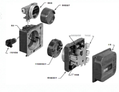
Example: DVC 6000 Series uses a digital algorithm for precise valve positioning. Requires feedback adjustment and HART 375/475 for debugging.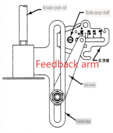
Reversing Valve
Classification
Two-position three-way, two-position four-way, two-position five-way, etc.
Function
Uses gas pressure to change direction; available in single and double air control types.
Fisher 377 Pressure Induction Solenoid Valve: Ensures actuator stability when air source pressure drops below a specific threshold.
Typical Gas Path – Fast Opening & Slow Closing
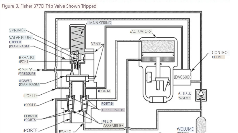
Normal System Operation
The solenoid valve is powered, and the pneumatic control valve remains in a conductive state, allowing controlled airflow.
Failure Mode
If the solenoid valve loses power, the pneumatic control valve rapidly exhausts compressed air to place the actuator in a safe position.
System Recovery
Once power is restored, the positioner resumes normal valve control.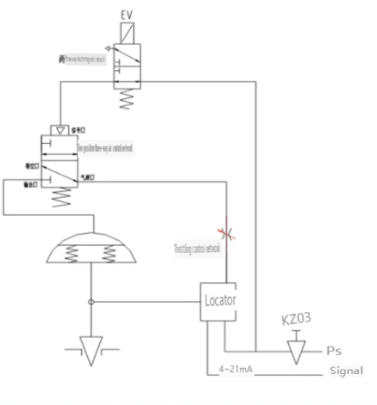


 English
 Arabic
 Russian
 French
 Spanish