
In the automatic control of modern chemical plants, control valves play a very important role. The production of these plants depends on the correct distribution and control of flowing media. Whether it is the exchange of energy, the reduction of pressure, or the simple addition of material to a container, certain final control elements are required to complete these controls.
1.Tips for extending the service life
1.1 Large Opening Operation
Ensure the regulating valve operates at the maximum opening as much as possible from the start, such as 90%. In this way, damage from gas turbidity and erosion occurs at the head of the valve core.
As the valve core is damaged, the flow rate increases, and the valve is correspondingly closed a bit more. This continuous damage allows for gradual closure, fully utilizing the entire valve core until the root of the valve core and the sealing surface are damaged and cannot be used.
At the same time, large opening operation has a larger throttling gap, which weakens erosion. This method increases the valve’s lifespan by 1-5 times or more compared to starting with the valve at a medium or small opening. For example, a chemical plant that adopted this method saw a 2-fold increase in valve life.
1.2 Reduce Valve Resistance Ratio (or Pressure Drop Ratio) S
Reducing S means increasing the system’s losses outside the regulating valve, thereby reducing the pressure drop across the valve. To ensure the flow passes through the regulating valve, the opening of the valve must be increased. Simultaneously, the pressure drop across the valve decreases, which also weakens cavitation and erosion.
Specific methods include: installing an orifice plate downstream of the valve to consume the pressure drop; closing manual valves in series on the pipeline until the regulating valve reaches a more ideal operating opening. For those who initially selected a valve that is too large and operates at a small opening, this method is very simple, convenient, and effective.
1.3 Reduce Diameter, Increase Operating Opening
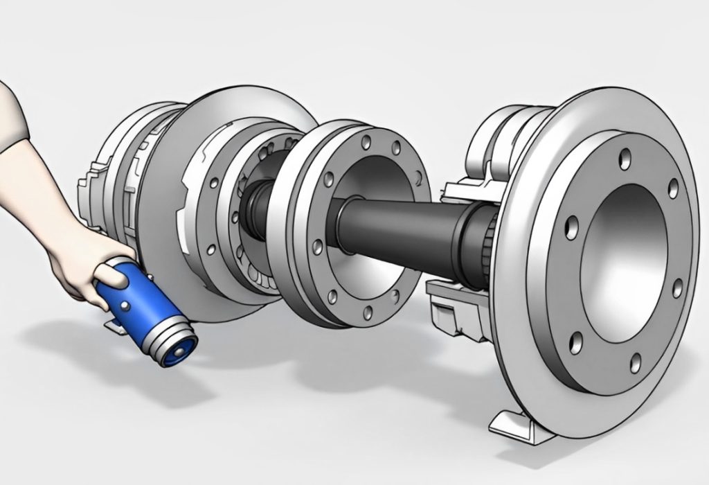
Increase the operating opening by reducing the diameter of the valve. Specific methods include:
(1) replacing the valve with one a size smaller, such as changing from DN32 to DN25;
(2) without changing the valve body, replacing the valve core and seat with a smaller diameter. For example, a chemical plant replaced the throttling component dg10 with dg8 during major repairs, which doubled the life of the valve.
1.4 Transfer Damage Location
Move the area of severe damage from critical positions to less important ones to protect the sealing and throttling surfaces of the valve core and seat. This can increase the service life of the valve.
1.5 Altering the Flow Direction
Flow-open type flows towards the direction of valve core opening, with cavitation and erosion mainly acting on the sealing surface, causing rapid damage to the root of the valve core and the sealing surface between the valve core and seat; flow-closed type flows towards the closing direction, with cavitation and erosion acting after the throttle, below the sealing surface of the valve seat, protecting the sealing surface and the root of the valve core, and extending the life.
Note: After changing from flow-open to flow-closed, there will also be a jump phenomenon (when the regulating valve is opened), and during the regulation process, the influence of vortices makes the control system unable to adjust smoothly. This method must be used with caution and comprehensive consideration.
1.6 Using Special Materials
To resist cavitation (destructive shapes like honeycomb small dots) and erosion (streamlined small grooves), special materials resistant to cavitation and erosion can be used to manufacture the throttling parts.
These special materials include 6YC—1, A4 steel, Stellite, hard alloys, etc. To resist corrosion, materials that are more corrosion-resistant and have certain mechanical and physical properties can be used.
These materials are divided into two categories: non-metallic materials (such as rubber, PTFE, ceramics, etc.) and metallic materials (such as Monel, Hastelloy, etc.).
1.7 Correctly Selecting Valve Structure
By changing the valve structure or selecting a valve with a longer life, the goal of improving the life can be achieved, such as selecting labyrinth valves, multi-stage valves, anti-cavitation valves, corrosion-resistant valves, etc. The advantages of using regulating valves in the process are:
(1) Quick action, able to complete various regulation commands in a timely manner;
(2) When used in combination with large cylinders, there is a greater torque driving force;
(3) Performance is relatively stable in harsh working environments, able to operate normally;
(4) High safety performance. Whether the regulating valve works normally and its responsiveness will directly affect the quality and efficiency of production. Therefore, the analysis and solutions to the factors influencing the failure of the regulating valve during use are particularly important.
2. Common Failures and Their Influencing Factors
There are some common failure and issue:
2.1 Blockage
Blockage is a frequent issue in control valves, often occurring in newly commissioned systems and during periods of re-commissioning after major repairs. This is due to the accumulation of impurities such as welding slag and iron chips inside the pipes at the throttle point and guide parts, causing blockage.
After a blockage occurs, the medium flow becomes obstructed, or the control valve experiences excessive tightening of the packing during maintenance, leading to increased friction and phenomena such as small signal inaction and large signal overaction.
2.2 Control Valve Leakage

Control valve leakage generally includes internal leakage, packing leakage, and leakage caused by deformation of the valve core and valve seat.
- Valve leakage is due to the improper length of the valve stem, with the stem of the air-open valve being too long, resulting in too short a distance upwards or downwards, causing a gap between the valve core and valve seat, not making full contact, and thus causing internal leakage. (2) Packing leakage, when the packing is installed into the packing box, exerts an axial pressure on the control valve. Due to the plastic deformation of the packing, radial pressure is generated, which makes close contact with the valve stem, but the contact is uneven. During the operation of the control valve, the stem and packing undergo axial movement. In high-temperature and high-pressure environments, affected by high-permeability fluid media, packing leakage is prone to occur.
(3) Leakage due to deformation of the valve core and valve seat, erosion and impact cause deformation, over time, there will be a mismatch between the valve core and valve seat, a gap exists between them, causing leakage due to not closing tightly.
2.3 Control Valve Oscillation
The causes of control valve oscillation include insufficient spring stiffness of the control valve, unstable output signals from the control valve causing rapid changes, the frequency of the control valve being the same as the system frequency, and severe vibration of the pipeline and base.
Improper selection of the control valve can also cause oscillation. When the control valve operates at a small opening, it produces severe changes in flow resistance, flow rate, and pressure. When these changes exceed the stiffness of the control valve, the stability of the control valve is reduced, and in severe cases, control valve oscillation occurs.
2.4 Control Valve Inaction
The failure symptoms of a control valve not operating include:
(1) No signal, no air source. The causes are that the air source is not turned on or has failed, the air duct is blocked, or the pressure reducing valve has failed due to blockage, or the compressor has malfunctioned;
(2) Air source present, no signal. The causes are that the positioner has failed due to a ruptured bellows causing air leakage, or the converter has failed;
(3) Positioner has no air source. The causes are that the filter, pressure reducing valve is blocked and has failed;
(4) Positioner has air source but no output. The causes are that the positioner’s throttle orifice is blocked and has failed;
(5) Signal present, no action. The causes are that the valve core has come off; the valve stem is bent or broken.
2.5 Unstable Control Valve Operation
The reasons for the instability of the control valve are:
(1) The compressor capacity is too small, causing the pressure reducing valve to fail, resulting in unstable air source pressure;
(2) The regulator is unstable, the time constant of the control system is inappropriate, resulting in unstable signal pressure;
(3) The friction resistance of the valve stem during movement is very large, causing sticking during contact;
(4) The ball valve in the amplifier of the positioner is worn by dirt and does not close tightly, especially when the air consumption is greatly increased, causing output oscillation.
2.6 Slow Control Valve Action
In the operation of the pneumatic diaphragm, damage and leakage occur, causing the valve stem to be sluggish in unilateral action;
The weak response performance of the positioner will lead to slow action of the control valve; there are rust and other blockages inside the control valve, causing blockage and making the axial movement of the control valve sluggish; poor quality or too tightly packed packing increases friction resistance, resulting in slow action of the control valve.
3. Fault Analysis of the Control Valve
3.1 How to deal with the blockage of the control valve?
Once the control valve is blocked, quickly open and close the control valve to use the fluid medium to wash away the blockages. You can also use a pipe wrench to clamp the valve stem tightly. Under the action of the external signal pressure, turn the valve stem back and forth with force to make the valve core pass through the blocked area.
If the blockage cannot be resolved at this time, the external source pressure and driving power can be appropriately increased, and repeated movement can be carried out. If the valve still cannot return to normal operation, professional personnel are required to disassemble the control valve for processing.
3.2 How to deal with the leakage of the control valve?
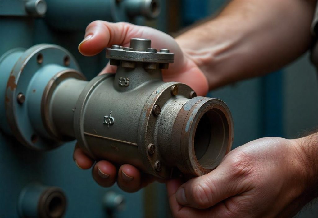
After the internal leakage of the control valve occurs, the length of the valve stem should be adjusted appropriately to make the length of the valve stem suitable and prevent further internal leakage. After the packing leaks, in order to make the packing installation more convenient, a chamfer should be made at the top of the stuffing box, and an anti-corrosion metal protection ring with a small gap should be added at the bottom of the stuffing box. The contact surface between the metal protection ring and the packing should not be a slope to prevent the packing from being pushed out due to the medium pressure.
The surface of the part where the stuffing box contacts the packing should be finely machined, which can improve the surface finish and reduce the wear of the packing.
Flexible graphite is the best choice for the packing because flexible graphite has high gas tightness, small friction force, little wear after long-term use, is easy to maintain, and has high pressure resistance and heat resistance.
If the valve core and valve seat are deformed and leaking, the materials of the valve core and valve seat should be strictly selected. Materials with high corrosion resistance should be chosen, and products with defects such as pitting and sand holes should be eliminated to ensure that the valve core and valve seat have a high sealing finish. When the valve core and valve seat are severely worn or damaged, a new valve should be replaced.
3.3 How to deal with the oscillation of the control valve?
When the control valve oscillates and the oscillation is relatively slight, the stiffness of the spring can be increased. For example, choose a spring with appropriate stiffness for the control valve. When the pipeline and the base vibrate violently, supports should be added to eliminate the vibration interference. If the frequency of the valve is the same as the system frequency, the control valve should be replaced.
3.4 What should be done if the control valve does not operate?
When the control valve does not operate, adjust the pressure reducing valve to make the pressure reach the specified air source pressure. Check the leakage points of the pipeline and the joint box of the positioner, and tighten or replace the joints and pipelines. Check the amplification hole and the throttle hole of the positioner and carry out maintenance.
3.5 How to deal with the unstable operation of the control valve?
If the operation of the control valve is unstable, check the signal pipeline, joints, sealing rings and other parts, and eliminate the leakage. Find the loose parts and tighten them. Add lubricating oil to the parts with large friction.
3.6 How to deal with the slow operation of the control valve?
If the control valve operates slowly, check the parts with large friction and reassemble them. Adjust the packing gland and replace the packing.
4. How should control valves be maintained?
During the operation of control valves, if a malfunction occurs, it can cause significant harm to the normal and stable operation of the system. Therefore, it is necessary to maintain the control valves to reduce the incidence of faults.
4.1 Reactive Maintenance
After a malfunction occurs in the control valve, it should be inspected to identify the cause of the fault and repaired promptly.
4.2 Preventive Maintenance
Control valves should be regularly cleaned to maintain their hygiene and the integrity and durability of their components. Regular flushing of the pipes should be conducted, paying attention to blockages and debris within the pipes. Fixed joints of the control valves should be inspected regularly to ensure good corrosion resistance and lubricity of the components.
During the installation of control valves, hard pulling and bending should be minimized to reduce pressure and prevent deformation. Maintain a distance between the control valve and the compressor to reduce vibration from the vibration source. Regular inspections of the control valves should be conducted, with close attention paid to their operation, checking for leaks in the packing, and regular addition of lubricating oil to the packing.
4.3 Predictive Maintenance
Obtain operational information of control valves through smart instruments or other diagnostic equipment to enhance the control quality and diagnostic functions of the valves. Through the diagnosis of smart instruments or other diagnostic equipment, problems with the control valves can be identified promptly, and timely solutions can be found for maintenance. Increase the development and use of intelligent valve positioners.

 English
 Arabic
 Russian
 French
 Spanish